
Steel for machine structure use for surface hardening and steel part for machine structure use

Inactive Publication Date: 2011-02-24
NIPPON STEEL & SUMITOMO METAL CORP
View PDF7 Cites 7 Cited by
  • Summary
  • Abstract
  • Description
  • Claims
  • Application Information

AI Technical Summary

Benefits of technology

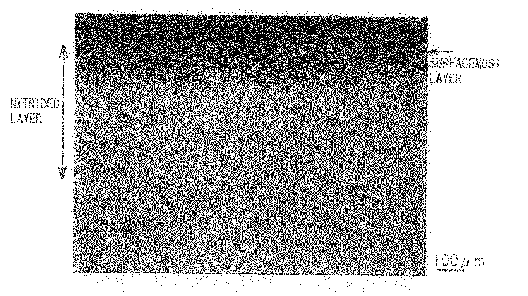
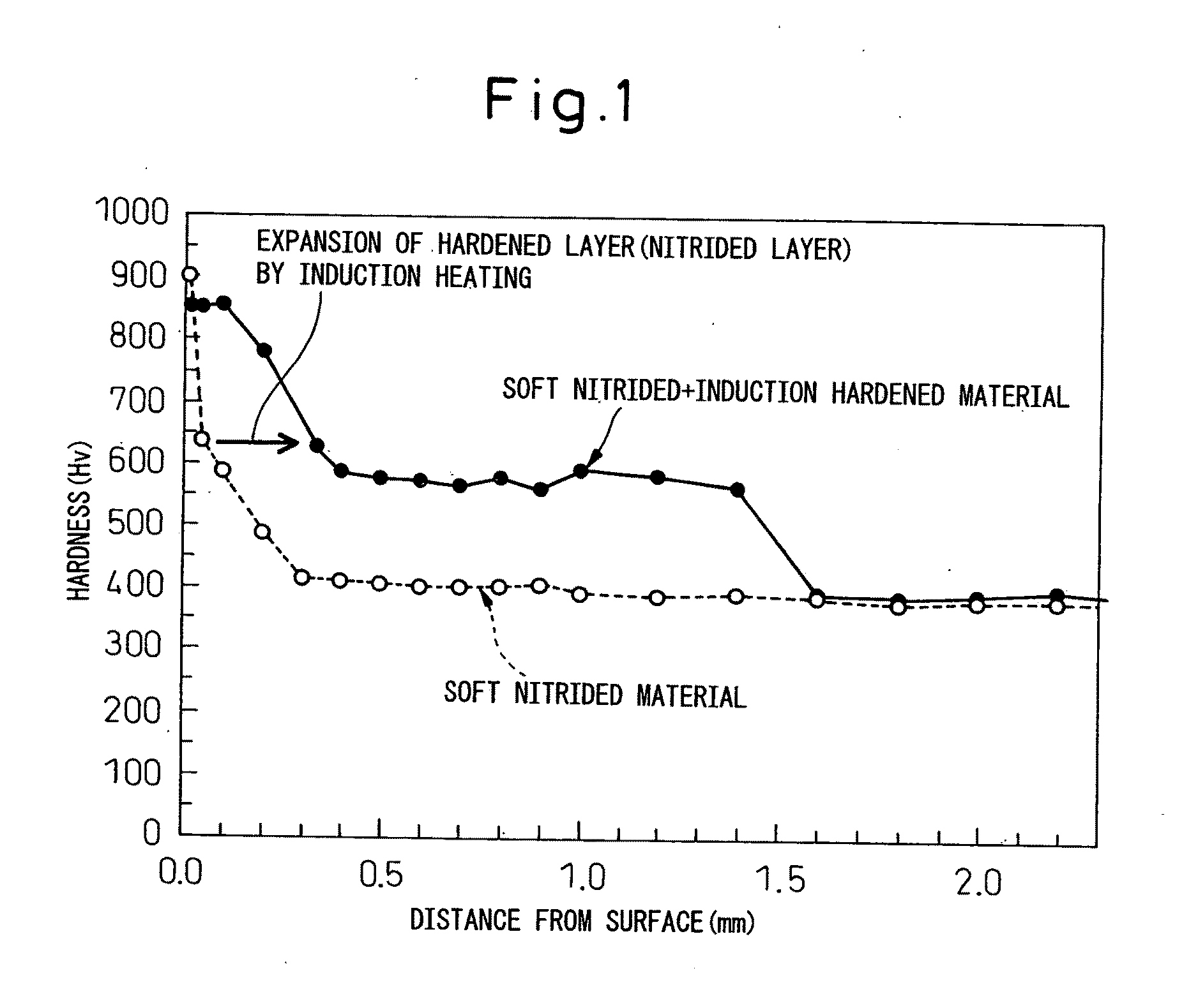
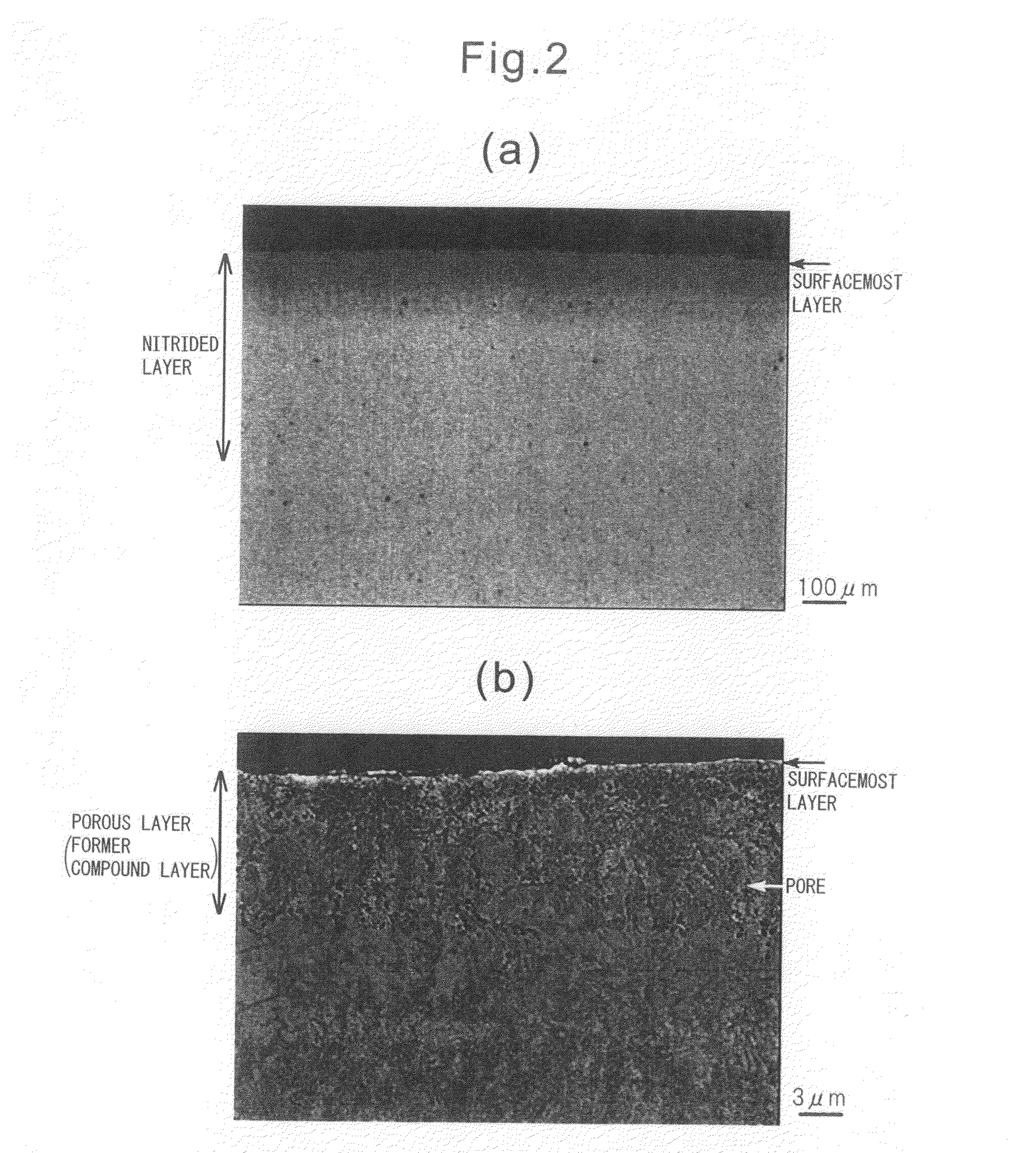
[0090]According to the present invention, it is possible to provide steel for structural use for surface hardening able to be applied to power transmission parts of automobiles etc. and possible to provide steel parts having high contact fatigue strength, in particular, gears, continuously variable transmission, constant velocity joints, hubs, and other steel parts for machine structures.

Problems solved by technology

However, carburized quenching is accompanied with austenite transformation at a 950° C. or so high temperature and is treated for a long period of 5 to 10 hours, in some cases, 10 hours or more, so larger heat treatment deformation due to coarsening of the crystal grains (distortion during quenching) is difficult to avoid.
If the amount of C in the steel becomes 0.8% or more, the internal hardness, which is unnecessary for improvement of the contact fatigue strength, also rises and the machineability remarkably deteriorates, so it is not possible to just increase the amount of C in the steel.
There are limits to improving the contact fatigue strength by just induction hardening.
However, with just soft nitriding, the hardened layer depth is shallow, so this cannot be used for transmission gears etc. to which a high contact pressure is applied.
However, with the method of PLT 1, the surface hardness is high, but the concentration of N in the nitrided layer is low, so the high temperature hardness is low, sufficient softening resistance cannot be obtained at the surface of the gear etc. becoming high in temperature during operation, and in the final analysis a high contact fatigue strength cannot be obtained.
However, the amounts of addition of elements with a high affinity with N which promote the breakdown and dispersion of nitrides are insufficient, so high temperature heating is required.
Therefore, the surface of the steel material is formed with an oxide layer to a remarkable extent and the mechanical properties end up greatly deteriorating.
Further, with the method of PLT 2, no consideration is given to the method of forming a thick compound layer, so good contact fatigue strength cannot be obtained under a high contact pressure.
However, in the method of production of PLT 3, no consideration is given to raising the contact fatigue strength by the formation of a required thickness of a nitrided layer.
However, in the heat treatment method of PLT 4, no consideration is given to raising the contact fatigue strength by the formation of a required thickness of a nitrided layer.
However, in the roller support shaft of PLT 5, no consideration is given to raising the contact fatigue strength by the formation of a required thickness of a nitrided layer.
However, the nitriding in the method of PLT 6 is performed at a high temperature of 600° C. or more, so the compound layer is thin.
Furthermore, the N concentration in it is low, so the amount of N diffusing due to decomposition at the time of induction hardening is also small.
In the end, with the nitriding of PLT 6, while a compound layer can be formed, formation of a thick, high N concentration nitrided layer is difficult, so even if combined with induction hardening, formation of a high softening resistance, good contact fatigue strength nitrided layer is not possible.
However, the steel for machine structure use of PLT 7 does not form the required thickness of nitrided layer and raise the contact fatigue strength, so even if this can be applied to a metal belt of a continuously variable transmission, it is difficult to apply this to gears of automatic transmissions, sheaves of continuously variable transmissions, constant velocity joints, hubs, and other power transmission parts subjected to high contact pressures.

Method used


Image

  • Steel for machine structure use for surface hardening and steel part for machine structure use
  • Steel for machine structure use for surface hardening and steel part for machine structure use
  • Steel for machine structure use for surface hardening and steel part for machine structure use

Examples


examples

[0205]Various steel materials with the chemical compositions shown in Table 1 and Table 2 (continuation of Table 1) were forged, then annealed, then machined to fabricate test pieces for use for roller pitching fatigue tests, that is, (a) small roller test pieces having cylindrical parts of diameters of 26 mm and widths of 28 mm and (b) large roller test piece having cylindrical parts of diameters of 130 mm and widths of 18 mm.

[0206]Furthermore, test pieces of a diameter of 26 mm and a length of 100 mm were fabricated for use for hardness tests for investigating the softening resistance by tempering.

TABLE 1Chemical composition (mass %)ExampleClassCSiMnPSCrMoWVAlO1Inv. ex.0.310.702.120.0250.0131.230.790.390.280.0510.0022Inv. ex.0.390.601.920.0280.0091.510.580.310.370.0380.0013Inv. ex.0.430.782.390.0150.0090.680.150.070.400.0830.0014Inv. ex.0.480.531.980.0120.0211.660.120.070.080.0770.0055Inv. ex.0.501.131.810.0140.0180.670.760.320.680.1600.0026Inv. ex.0.531.392.540.0170.0141.410.800....


PUM

PropertyMeasurementUnit
Temperatureaaaaaaaaaa
Lengthaaaaaaaaaa
Lengthaaaaaaaaaa

Abstract

Steel for machine structure use for surface hardening containing, by mass %, C: 0.3 to 0.6%, Si: 0.02 to 2.0%, Mn: 1.5% to 3.0%, W: 0.0025 to 0.5%, Al: 0.001 to 0.5%, N: 0.003 to 0.02%, S: 0.0001 to 0.025%, P: 0.0001 to 0.03%, and O: 0.0001 to 0.0050%, having an Mn / S of 70 to 30000, and having a balance of substantially Fe and unavoidable impurities.

Description

TECHNICAL FIELD[0001]The present invention relates to steel for machine structure use for surface hardening and in particular a steel part for machine structure use having a high contact fatigue strength applied to a gear, continuously variable transmission, constant velocity joint, hub, or other power transmission part for an automobile etc.BACKGROUND ART[0002]Steel parts for machine structure use, for example, gears of automatic transmissions, sheaves of continuously variable transmissions, constant velocity joints, hubs, bearings and other power transmission parts require high contact fatigue strength.[0003]In the past, in general, the above parts have been obtained by working materials such as JIS SCr420, SCM420, or other C: 0.2% or so case hardened steel into parts, then treating them by carburized quenching to form C: 0.8% or so martensite structure hardened layers on the surfaces of the parts and improve the contact fatigue strength.[0004]However, carburized quenching is acco...

Claims


Application Information

Patent Timeline
IPC IPC(8): C23C8/26
CPCC21D1/06B32B15/04C21D9/32C21D2211/004C21D2211/005C21D2211/008C21D2211/009C22C38/001C22C38/02C22C38/04C22C38/06C22C38/12C22C38/22C22C38/24C22C38/38C23C8/26C23C8/32C21D1/10C22C38/18Y02P10/25C22C38/002C22C38/32
Inventor MIZUNO, ATSUSHIHASHIMURA, MASAYUKISAITOH, HAJIMEKOZAWA, SHUJIMIYANISHI, KEI
Owner NIPPON STEEL & SUMITOMO METAL CORP
Learn More