
Substrate glass for leds with layer containing scattering particles and method for production thereof

a technology of scattering particles and substrate glass, which is applied in the field of composite materials, can solve the problems of reducing efficiency, limiting subsequent processing steps, and low thermal and mechanical resistance, and achieves the effect of reducing the loss of light due to total reflection and being easy to produ

Inactive Publication Date: 2011-02-24
SCHOTT AG
View PDF5 Cites 19 Cited by
  • Summary
  • Abstract
  • Description
  • Claims
  • Application Information

AI Technical Summary

Benefits of technology

Thus the object underlying the invention is to make available a substrate for LED's that is easy to produce, in which losses of light due to total reflections are reduced.
The composite material according to the invention is also to have adequate thermal and mechanical resistance and adequate durability.
The hybrid polymer matrix is formed as an organic / inorganic hybrid polymer matrix. Because of the inorganic constituents, a coating can be provided with a high temperature stability and with a high long-term durability. At the same time, the index of refraction of the composite is usually increased by the inorganic constituents of the matrix. Furthermore, the hybrid polymer matrix is distinguished from purely organic layered systems by greater strength as a rule.
The coating usually has a lower index of refraction than the substrate to reduce or prevent total reflections at the interface of the substrate coating.
The nanoparticles in a preferred embodiment of the invention, in particular in the configuration as oxide particles, have an average diameter between 0.5 and 200 nm, preferably between 4 and 25 nm. Especially in the last-mentioned range, the nanoparticles, particularly in the configuration as oxide particles, are not optically active within the coating but contribute primarily to increasing the index of refraction.
The sol-gel material can be applied readily even on large surfaces, for example, by dipping, spraying, roller coating, flooding, ink jet, pad printing, flexographic printing, screen printing, etc.

Problems solved by technology

The drawback here is that because of the polarizing mechanism of action, the efficiency is reduced by the previously described losses of light.
An important drawback of such layered systems based on organic polymers is the low thermal and mechanical resistance, which limits subsequent processing steps, and in many cases the lack of long-term stability.
For this reason, layers based on organic polymers usually lead to high losses of light because of total reflections at the substrate / polymer layer interface.

Method used


Image

  • Substrate glass for leds with layer containing scattering particles and method for production thereof
  • Substrate glass for leds with layer containing scattering particles and method for production thereof
  • Substrate glass for leds with layer containing scattering particles and method for production thereof

Examples


Embodiment Construction

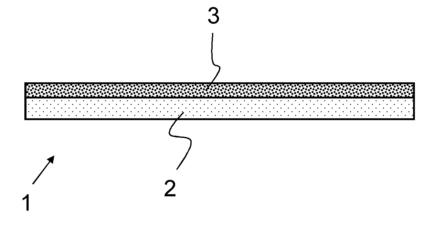
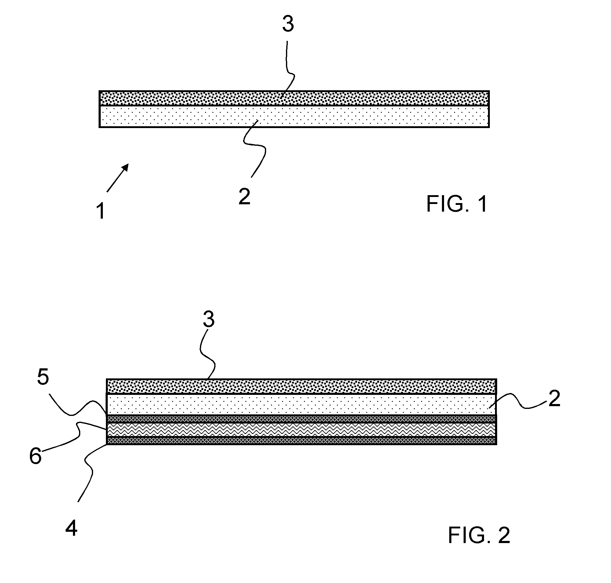
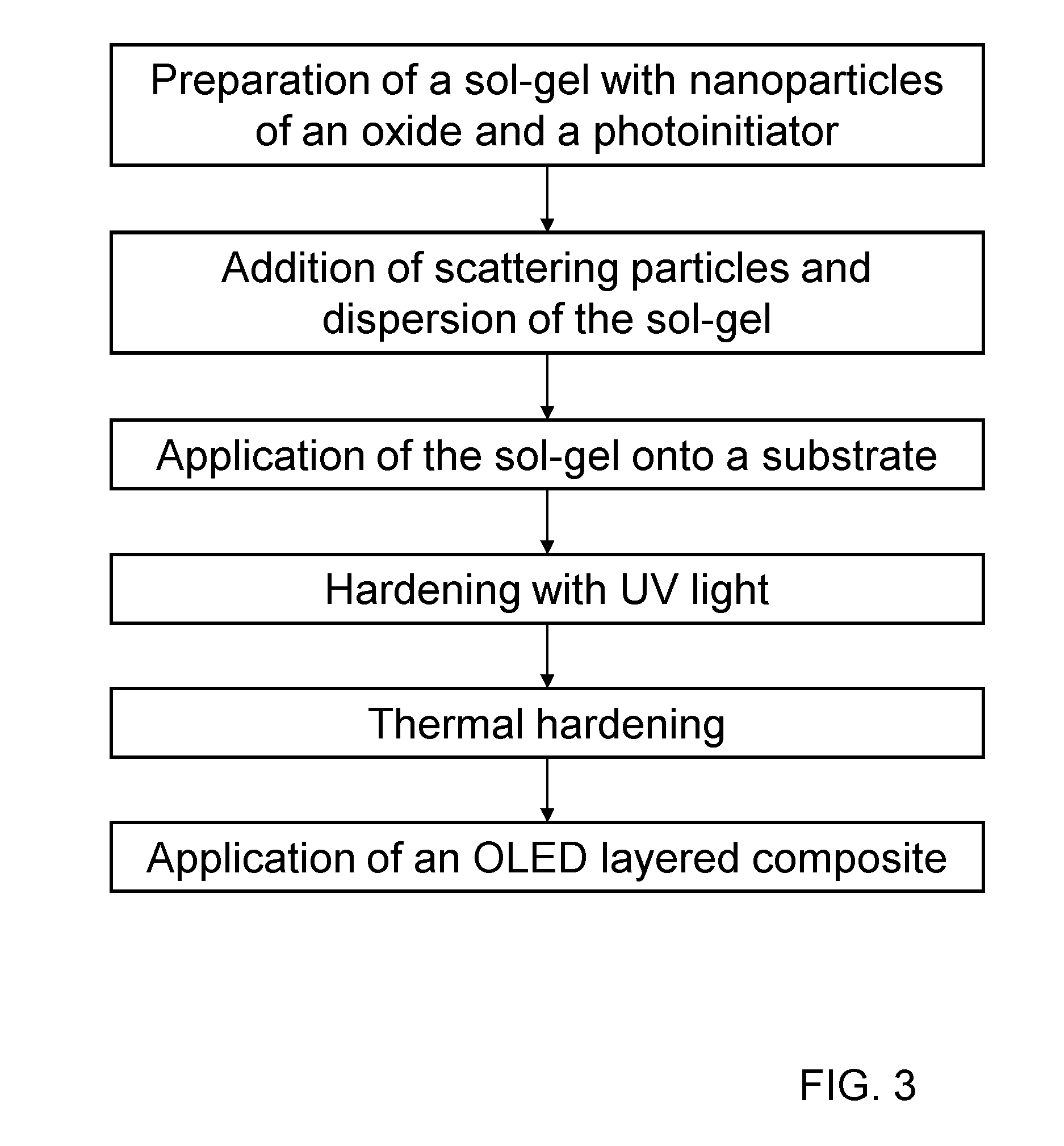
The invention will be explained in further detail below with reference to FIGS. 1 to 3.

FIG. 1 shows a composite material 1 that comprises a glass substrate 2 and a coating 3.

The coating 3 is a sol-gel layer to which are added scattering particles of an oxide with an average diameter between 100 nm and 200 μm, and that also comprises oxide nanoparticles to increase the index of refraction.

Losses of light due to total reflection are reduced by the coating 3, which has an index of refraction >1.7.

FIG. 2 shows an OLED that comprises the composite material.

Besides the composite material composed of the substrate 2 and the coating 3, the OLED also comprises an emitter layer 6 that is positioned between anode 4 and cathode 5.

The layers of the OLED 4, 5, 6 are directly deposited on the substrate glass 2. In this example of embodiment the coating 3 comprising the scattering particles is positioned on the side opposite the emitter layer 6. It is to be understood that the coating 3 can be adja...


PUM

PropertyMeasurementUnit
Temperatureaaaaaaaaaa
Fractionaaaaaaaaaa

Abstract

A composite material for LED's is provided. The composite material has a coating comprising scattering particles with an index of refraction greater than 1.6.

Description

CROSS REFERENCE TO RELATED APPLICATIONSThis application claims benefit under 35 U.S.C. §119(a) of German Patent Application No. 10 2009 036 134.0, filed Aug. 5, 2009, the entire contents of which are incorporated herein by reference.BACKGROUND OF THE INVENTION1. Field of the InventionThe invention relates to a composite material that is designed in particular as a substrate glass for light emitting diodes (“LED's”), and a method for the production thereof.2. Description of Related ArtOrganic LED's (usually called OLED's) have been continuously further developed improved in recent years, which addresses efficiency and service life. Nevertheless there is a great need for improving such LED's, especially to be able to make products available that are competitive with conventional LED technology.Usually, only about 20 to 25% of the light produced in the emitter layer is emitted by LED's. A large fraction of the light generated remains in guided optical modes within the organic layers or...

Claims


Application Information

Patent Timeline
IPC IPC(8): B32B7/02C03C17/00B32B17/00B05D5/06B05D3/06B82Y30/00B82Y40/00
CPCG02B5/02Y10T428/24942H01L51/5268Y10T428/25H10K50/854H10K2102/331
Inventor BOCKMEYER, MATTHIASRUDIGIER-VOIGT, EVELINE
Owner SCHOTT AG
Learn More