
Vacuum-sealing-type flexible-film primary battery and method of manufacturing the same

a flexible film, vacuum sealing technology, applied in the direction of primary cell details, cell components, electrochemical generators, etc., can solve the problems of long life, leakage or dryness of the electrolyte contained in the cell, and the inability to completely cut off the transmittance of moisture in the gas or air, and achieve high corrosion resistance to an electrolyte

Active Publication Date: 2011-02-24
ELECTRONICS & TELECOMM RES INST
View PDF14 Cites 45 Cited by
  • Summary
  • Abstract
  • Description
  • Claims
  • Application Information

AI Technical Summary

Benefits of technology

[0016]The present invention is directed to a flexible-film primary battery in which a pouch formed of a polymer-metal composite film, which completely cuts off transmission of external gases and moisture and has high corrosion resistance to an el

Problems solved by technology

In this case, the internal power source may use a power device appropriate for the RFID tag, which is compact and lightweight and has a long lifespan.
However, although most polymer films may drop transmittance of moisture in a gas or air to a predetermined level or lower, it is impossible to completely cut off the transmittance of moisture in the gas or air.
In the long run, this may result in leakage or dryness of the electrolyte contained in a cell.
In addition, since most polymer films, except a polyolefin film, have low corrosion resistances to strong acids or strong bases, a direct contact of the polymer films with the electrolyte over a long period may lead to corrosion of the polymer films.
These problems may detrimentally affect the durability, retention periods, and lifespans of film-type batteries, thereby greatly reducing the performances thereof.
Since the PP inner layer of the pouch has a low surface energy and a hydrophobic characteristic, the PP inner layer have a poor wettability in an organic solvent and have a poor coating characteristic, so that it is impossible to directly coat the conductive carbon layer on the PP inner layer.
This is due to the fact that the PP inner layer of the pouch is neither compatible nor miscible with any polar polymer that is currently known as a binder of an electrode slurry.
Unlike in a conventional method in which electrode plates are laminated and wound to fabricate a cell, a film-type battery is manufactured by simply laminating positive and negative plates between which an electrolyte layer is inserted, thus causing separation or bad contact between the electrode plate and the electrolyte layer.
Accordingly, when the conventional manufacture of batteries is applied to the thin film-type battery, it is difficult to overcome high process costs due to a multi-stage manufacturing process and reduce the unit cost of production of the film-type batteries.

Method used


Image

  • Vacuum-sealing-type flexible-film primary battery and method of manufacturing the same
  • Vacuum-sealing-type flexible-film primary battery and method of manufacturing the same
  • Vacuum-sealing-type flexible-film primary battery and method of manufacturing the same

Examples


embodiment 1

of 1.5V Film-Type Manganese (Mn) Primary Battery

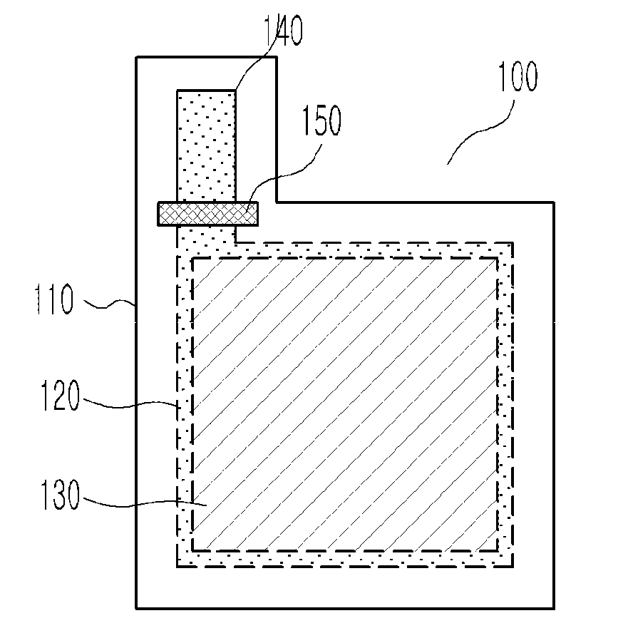
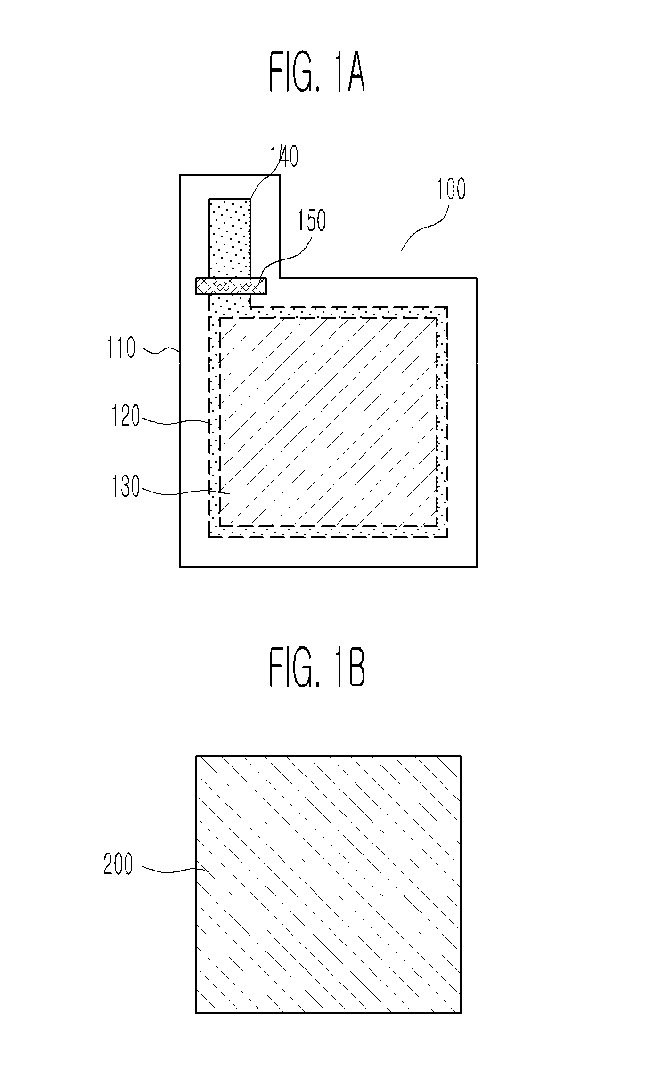
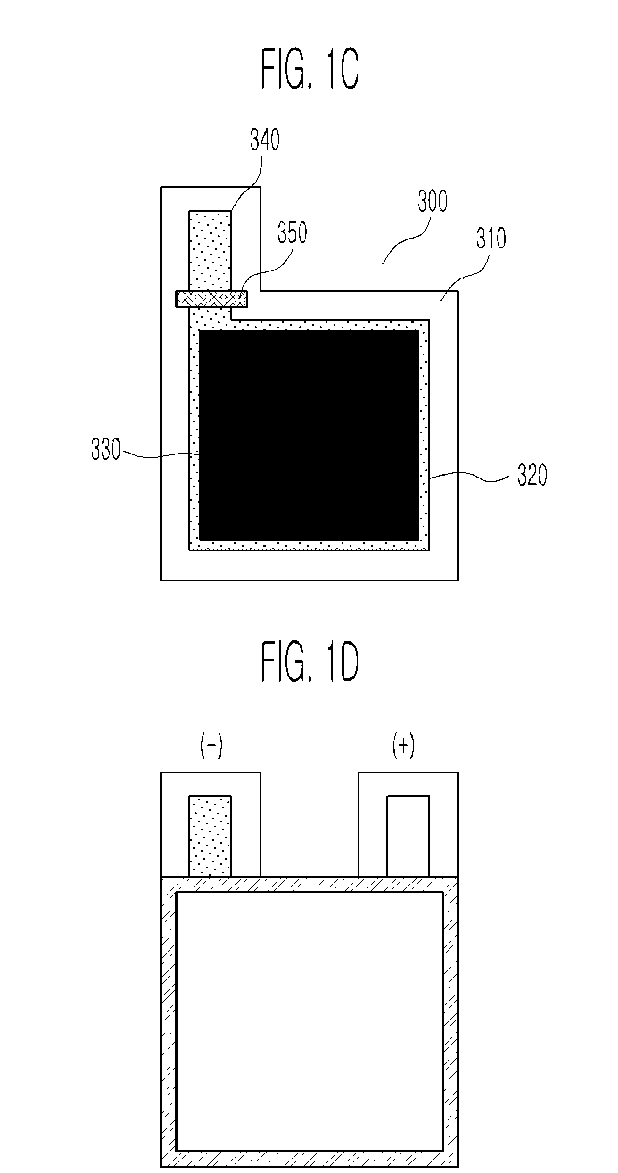
[0075]An inner layer was formed of cast polypropylene (c-PP) to a thickness of about 35 mm, an outer layer was formed of nylon to a thickness of about 15 mm, and 30 mm-thick aluminum (Al) foil was inserted between the inner and outer layers. The inner layer, the Al foil, and the outer layer were laminated to form a 75 mm-thick Al pouch. An inner surface of the Al pouch was hydrophilic-treated using a corona discharger in an atmospheric environment until a surface energy reached about 50 dyne / cm or higher. The hydrophilic-treated inner surface of the Al pouch lost its peculiar gloss and became rough. It could be confirmed that when drops of water fell on the surface-treated inner surface of the Al pouch, they did not stand but spread out to facilitate formation of a coating layer.

[0076]Jelly-like highly viscous carbon paste, which was manufactured by dissolving 5% by weight PVDF in N-methyl pyrrolidone (NMP) and adding 95% by weight gra...

embodiment 2

of 3V Film-Type Lithium Primary Battery

[0081]Positive and negative electrode collectors were formed in the same manner as in Embodiment 1, and the positive electrode collector was coated with the same positive electrode active material as in Embodiment 1, thereby forming a positive electrode plate. However, to form a negative electrode plate, 50 μm-thick Li foil was cut to an area of 4.3 cm×4.3 cm, placed on the negative electrode collector, and bonded to the negative electrode collector under pressure.

[0082]Also, a polymer electrolyte layer was formed in the same manner as in Embodiment 1 except that a vinylidene fluoride-HFP copolymer was dissolved in an NMP co-solvent and 25% by weight hydrophobic silica based on the total weight of a polymer matrix was added, and the resulting solution was coated on both 16 mm-thick PE porous layers to a thickness of about 5 mm or more to form a triple composite layer. In this case, an electrolyte was injected and activated in the same manner as...


PUM

PropertyMeasurementUnit
Lengthaaaaaaaaaa
Lengthaaaaaaaaaa
Adhesion strengthaaaaaaaaaa

Abstract

Provided are a vacuum-sealing-type flexible-film primary battery and a method of manufacturing the same. The primary battery includes a battery assembly comprising a positive electrode plate including a positive electrode collector having a first conductive carbon layer disposed on a surface-treated inner surface of a first pouch and a positive electrode layer disposed on the first conductive carbon layer of the positive electrode collector, a negative electrode plate including a negative electrode collector having a second conductive carbon layer disposed on a surface-treated inner surface of a second pouch and a negative electrode layer disposed on the second conductive carbon layer of the negative electrode collector, and an adhesion / post-injection polymer electrolyte layer interposed between the positive electrode plate and the negative electrode plate, wherein the battery assembly is completely sealed. The flexible-film primary battery may employ the pouch as a collector film to improve flexibility. Also, the flexible-film primary battery may be completely sealed using the pouch to improve a retention period and cell performance. Furthermore, the flexible-film primary battery may be manufactured using a screen printing technique, thereby facilitating a roll-to-roll sequential process.

Description

CROSS-REFERENCE TO RELATED APPLICATION[0001]This application claims priority to and the benefit of Korean Patent Application Nos. 10-2009-0076886, filed Aug. 19, 2009 and 10-2009-0098147 filed Oct. 15, 2009, the disclosure of which are incorporated herein by reference in its entirety.BACKGROUND[0002]1. Field of the Invention[0003]The present invention relates to a vacuum-sealing-type flexible-film primary battery and a method of manufacturing the same, and more specifically, to a vacuum-sealing-type flexible-film primary battery, which uses a pouch as a collector substrate and employs a non-metal terminal technique, and a method of manufacturing the primary battery.[0004]2. Discussion of Related Art[0005]In recent years, a vast amount of research has been conducted on active radio frequency identification (RFID) tag technology. It is expected that the active RFID tag technology, which has a far-reaching influence on a wide variety of fields including digital TVs, home networks, and ...

Claims


Application Information

Patent Timeline
IPC IPC(8): H01M6/02H01M6/00H01M4/485
CPCH01M6/181H01M10/0472H01M4/76Y10T29/4911H01M4/366H01M6/40H01M6/02Y02E60/10
Inventor LEE, YOUNG GIKIM, KWANG MANCHOI, MIN GYULEE, SANG HYOKIM, JONG DAE
Owner ELECTRONICS & TELECOMM RES INST
Learn More