System and method for protection of scr catalyst

a technology of scr catalyst and protection system, which is applied in the field of system and method for protecting scr catalyst, can solve the problems of ammonia level, precious metal catalysts less attractive, and potential to oxidize, and achieve the effect of preventing the plugging, blocking and/or contamination of scr catalysts

Inactive Publication Date: 2011-03-03
THE BABCOCK & WILCOX CO
View PDF11 Cites 11 Cited by
  • Summary
  • Abstract
  • Description
  • Claims
  • Application Information

AI Technical Summary

Benefits of technology

[0002]The present invention relates generally to the field of emission control equipment for boilers, heaters, kilns, or other flue gas-, or combustion gas-, generating devices (e.g., those located at power plants, processing plants, etc.) and, in particular to a new and useful method and apparatus for preventing the plugging, blockage and / or contamination of an SCR catalyst. In another embodiment, the method and apparatus of the present invention is designed to protect an SCR catalyst from plugging and / or blockage from large particle ash that may be generated during combustion.

Problems solved by technology

Rather, it is a practical limit set to prevent excessive levels of ammonia slip.
The major drawback of the base metal catalyst is its potential to oxidize SO2 to SO3; the degree of oxidation varies based on catalyst chemical formulation.
However, SO2 oxidation to SO3 and high material costs often make precious metal catalysts less attractive.

Method used


Image

  • System and method for protection of scr catalyst
  • System and method for protection of scr catalyst
  • System and method for protection of scr catalyst

Examples


Embodiment Construction

[0026]While the present invention will be described in terms of SCR systems which use ammonia as the NO reducing agent, since ammonia is frequently preferred for economic reasons, the present invention is not limited to ammonia based systems. The concepts of the present invention can be used in any system which uses an ammoniacal compound. As used in the present disclosure, an ammoniacal compound is a term meant to include compounds such as urea, ammonium sulfate, cyanuric acid, and organic amines as well as ammonia (NH3). These compounds could be used as reducing agents in addition to ammonia, but as mentioned above, ammonia is frequently preferred for economic reasons. Some non-ammoniacal compounds such as carbon monoxide or methane can be used as well, but with loss in effectiveness.

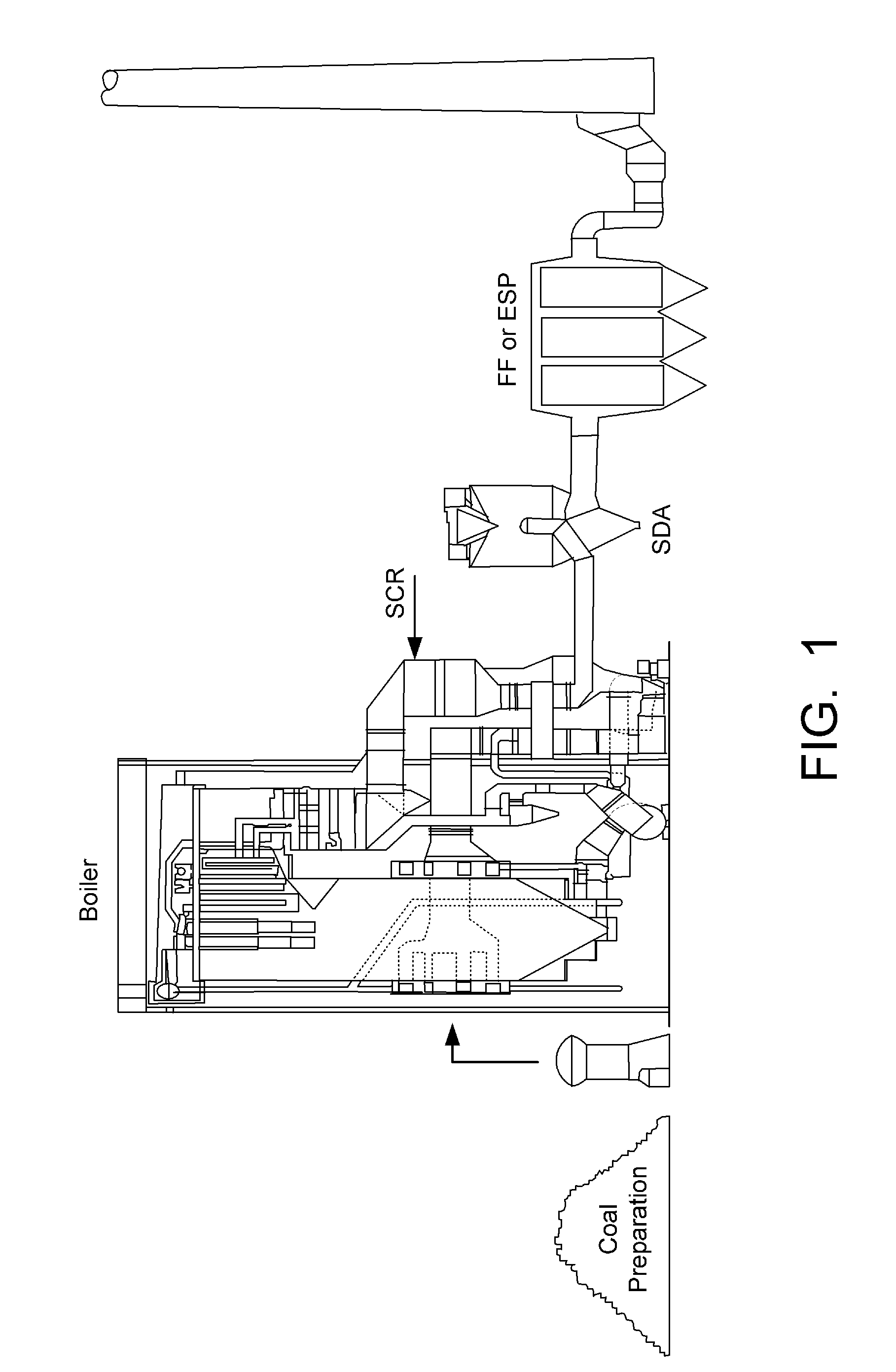
[0027]Although the present invention is described in relation to a boiler, or a fossil fuel boiler, it is not limited solely thereto. Instead, the present invention can be applied to any combustion so...


PUM

PropertyMeasurementUnit
mean particle sizeaaaaaaaaaa
temperatureaaaaaaaaaa

Abstract

The present invention relates generally to the field of emission control equipment for boilers, heaters, kilns, or other flue gas-, or combustion gas-, generating devices (e.g., those located at power plants, processing plants, etc.) and, in particular to a new and useful method and apparatus for preventing the plugging, blockage and/or contamination of an SCR catalyst. In another embodiment, the method and apparatus of the present invention is designed to protect an SCR catalyst from plugging and/or blockage from large particle ash that may be generated during combustion.

Description

FIELD AND BACKGROUND OF THE INVENTION[0001]1. Field of the Invention[0002]The present invention relates generally to the field of emission control equipment for boilers, heaters, kilns, or other flue gas-, or combustion gas-, generating devices (e.g., those located at power plants, processing plants, etc.) and, in particular to a new and useful method and apparatus for preventing the plugging, blockage and / or contamination of an SCR catalyst. In another embodiment, the method and apparatus of the present invention is designed to protect an SCR catalyst from plugging and / or blockage from large particle ash that may be generated during combustion.[0003]2. Description of the Related Art[0004]NOx refers to the cumulative emissions of nitric oxide (NO), nitrogen dioxide (NO2) and trace quantities of other nitrogen oxide species generated during combustion. Combustion of any fossil fuel generates some level of NOx due to high temperatures and the availability of oxygen and nitrogen from b...

Claims


Application Information

Patent Timeline
Patent Type & Authority Applications(United States)
IPC IPC(8): B01D45/14
CPCB01D51/10B01D53/8631B01D2258/0283Y02E50/12F23J2217/30F23J2219/10F23J15/02Y02E50/10
Inventor IANNACCHIONE, STEVEN P.
Owner THE BABCOCK & WILCOX CO
Why Eureka
Try Eureka