
Single nanoparticle tracking spectroscopic microscope

a single particle, spectroscopic microscope technology, applied in the field of single particle tracking system, can solve the problems of not providing a direct correlation between local dynamics and the position of the molecule or particle, and it is extremely difficult, if not impossible, to observe using conventional spectroscopy

Active Publication Date: 2011-03-10
RGT UNIV OF CALIFORNIA
View PDF4 Cites 15 Cited by
  • Summary
  • Abstract
  • Description
  • Claims
  • Application Information

AI Technical Summary

Benefits of technology

[0010]Unlike active trapping approaches, the method disclosed herein is noninvasive and provides nanometer spatial resolution with sub-millisecond response time. In one arrangement, near-infrared (NIR) light scattered off a gold nanoparticle, to which a particle of interest can be tethered, provides a feedback signal that can be used for tracking. In other arrangements, fluorescence or photoluminescence from a single particle of interest can be tracked without using gold nanoparticles. An NIR light source has many advantages over a visible light source: photo-luminescence of the host material is reduced, depth of penetration is greater, especially when working with turbid samples, photo-damage of biological samples is minimized, and separation from the usual near-UV or visible excitation light used for SMS is easily achieved by spectral filtering.
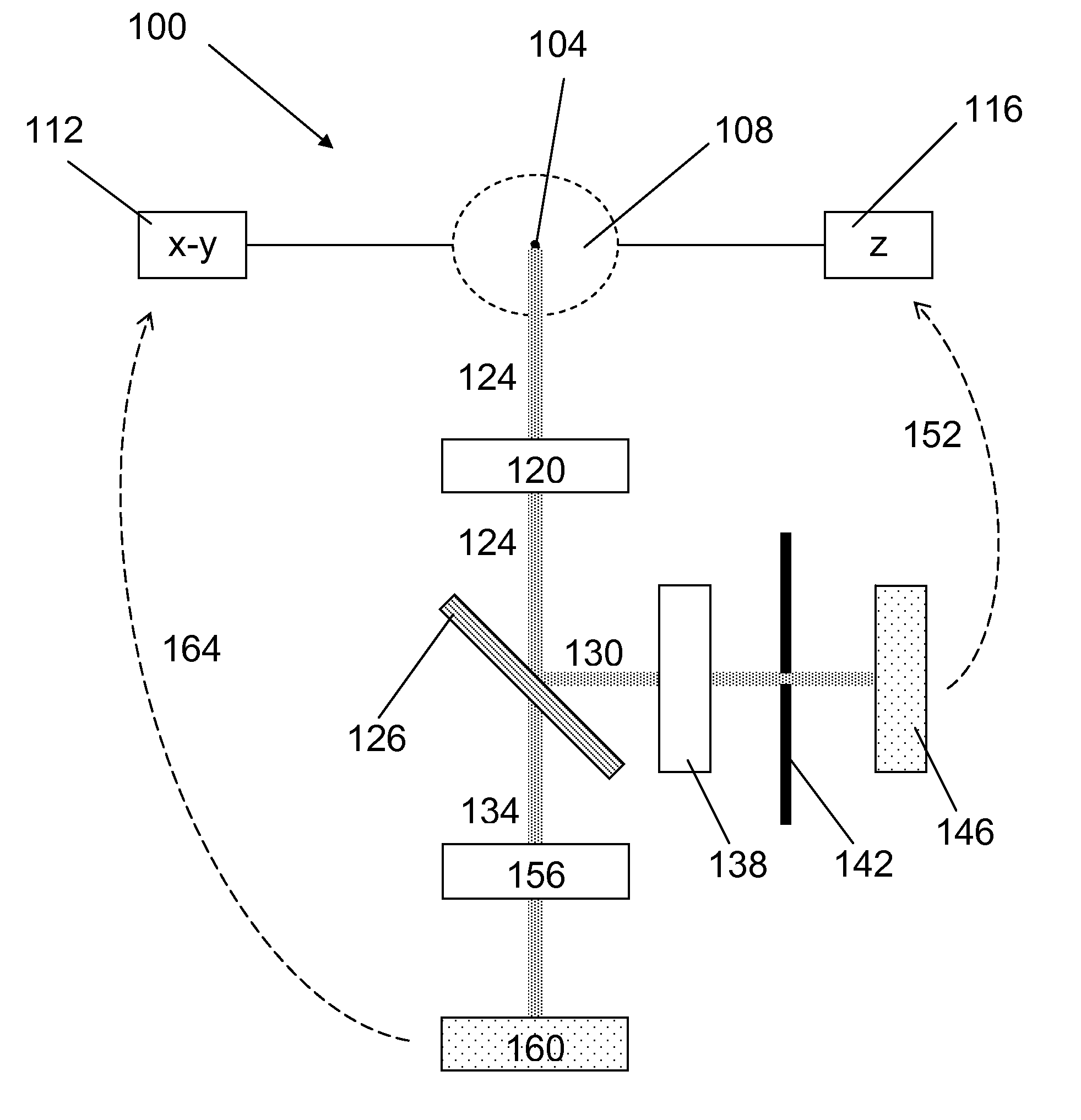
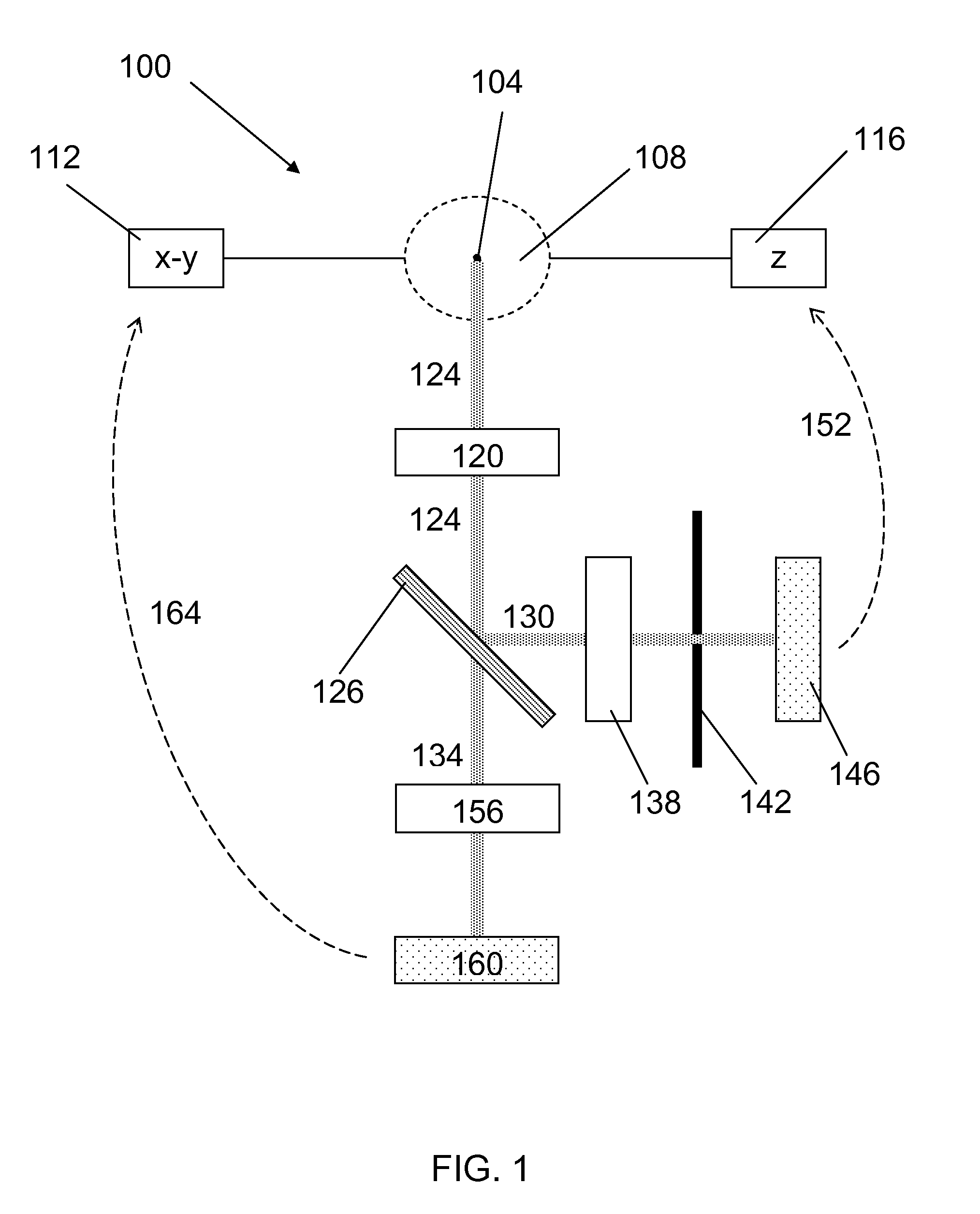
[0016]Along the path 134, a third radiation-gathering component 156 directs the radiation 134 onto a position-sensitive radiation detector 160. The radiation detector 160 is of a type suitable for detecting the radiation 134. Examples of radiation detectors have been given above. A second feedback control mechanism 164 provides communication from the detector 160 to the x-y control 112. The feedback control mechanism 164 provides information to the x-y control 112 about movement of the particle 104 in the x direction and in the y direction so that the x-y control 112 can adjust the position of the particle 104 in the x direction and in the y direction as desired. The x-y control 112 moves the particle-holding device 108 to counteract the movement of the particle in the x-y plane so the position of the particle in the x-y plane is stable. In some arrangements, the particle stability in the x or y direction is within ±50 nm. In some arrangements, the particle stability in the x or y direction is within ±30 nm. In some arrangements, the particle stability in the x or y direction is within ±15 nm. In other arrangements, the particle stability in the x or y direction is within ±5 nm.
[0024]Some particles or molecules can be difficult to track because they do not offer much contrast against background. To increase contrast and make tracking easier, a molecule of interest can be tethered to a metallic nanoparticle. Light scattered from the nanoparticle is collected by the tracking objective, and the intensity of the collected light is used in feedback loops (for the particle tracking system) to keep the particle in the focal volume. It is still possible to perform SMS on the tethered molecule as fluorescence photons can be collected by the SMS objective from which single molecule time trajectory and spectral properties can be acquired.
[0025]The use of a metallic nanoparticle as a tracer has several advantages. The small size of the nanoparticle, on the order of 40 nm or less, provides a non-obstructive biological label to cellular processes when attached to a biological macromolecule. Scattered light from a 60-nm gold particle may be equivalent to up to 3×10⁵ times greater than the light emitted by a standard fluorescent dye, or by molecular fluoresce, depending on the wavelength used. A signal of this intensity is very useful in the particle tracking system. Furthermore, nanoparticles do not suffer from blinking or photobleaching, which can occur with fluorescent labels. Detected light from gold particles results from scattering, so it is possible to choose an illumination source, such as a laser in the near infrared region, that is biologically benign. The choice of an illumination source when using fluorescent labels is less flexible due to restrictions in excitation wavelengths. The wavelength of the tracking radiation can be chosen to avoid interference with SMS, if that is used in the system.
[0030]A single molecule spectroscopy (SMS) system 605 is similar to the design used in standard confocal SMS configurations. Fluorescence signals as stimulated by excitation light and focused down to a diffraction-limited spot are collected from the focal volume and focused through a pinhole onto a sensitive photon detector such as an avalanche photodiode, after passing through an emission filter. The pinhole can suppress background so that emission from a single molecule is easier to observe. Because of the single particle tracking system, the target particle remains in focus even as it moves in three dimensions, thus making it possible to perform this kind of SMS investigation. For the spectroscopic probe, a 532-nm laser beam 618 from a solid-state laser (included within the SMS system 605 in FIG. 6) is coupled into the back aperture of the objective lens 630 through a long-pass dichroic mirror 632. The objective lens 630 focuses the light at the sample 622. A second, short-pass dichroic mirror 637 can separate the NIR tracking light 613 from the optical output of the green interrogation beam (i.e., the fluorescence signal from the sample 622. The optical output is focused by a 180-mm tube lens 640 in the microscope and detected by an APD 647.

Problems solved by technology

This widely used experimental scheme, however, does not provide a direct correlation between local dynamics and the position of the molecule or particle in three dimensions, which can be a critical in understanding the link between microscopic processes and macroscopic phenomena.
It is extremely difficult, if not impossible, using conventional spectroscopy, to observe the sequence of events in processes such as conformational dynamics of protein molecules and intermolecular interactions between enzymes and substrates.

Method used


Image

  • Single nanoparticle tracking spectroscopic microscope
  • Single nanoparticle tracking spectroscopic microscope
  • Single nanoparticle tracking spectroscopic microscope

Examples


Embodiment Construction

[0009]In some embodiments of the invention, a system tracks a particle non-invasively and provides simultaneous particle position information. In other embodiments, single-molecule spectroscopy (SMS) is also performed on the particle. In other embodiments, the system tracks a nanoparticle while providing concurrent sequential position information and SMS measurements as the nanoparticle moves. In some arrangements, the movement, trajectory, and reaction pathways of single nanoparticles, fluorophores or molecules in diffusive, confined, or directed motions in complex systems, such as biological systems, can be quantified. Methods for using the systems are also disclosed.

[0010]Unlike active trapping approaches, the method disclosed herein is noninvasive and provides nanometer spatial resolution with sub-millisecond response time. In one arrangement, near-infrared (NIR) light scattered off a gold nanoparticle, to which a particle of interest can be tethered, provides a feedback signal ...


PUM


Abstract

A system that can maintain and track the position of a single nanoparticle in three dimensions for a prolonged period has been disclosed. The system allows for continuously imaging the particle to observe any interactions it may have. The system also enables the acquisition of real-time sequential spectroscopic information from the particle. The apparatus holds great promise in performing single molecule spectroscopy and imaging on a non-stationary target.

Description

CROSS-REFERENCE TO RELATED APPLICATIONS[0001]This application claims priority as a continuation application to PCT International Patent Application No. PCT / US2006 / 062578, filed Dec. 22, 2006, which claims priority to U.S. Provisional Patent Application Ser. No. 60 / 753,621, filed Dec. 22, 2005, both of which are hereby incorporated by reference.STATEMENT OF GOVERNMENTAL SUPPORT[0002]The invention described and claimed herein was made utilizing funds supplied by the U.S. Department of Energy under Contract No. DE-AC02-05CH11231. The U.S. government has certain rights in this invention.TECHNICAL FIELD[0003]This invention relates generally to a system for tracking a single particle and more specifically, to systems and methods for imaging and analyzing single particles.BACKGROUND ART[0004]Spectroscopic studies at the single-molecule or single-particle levels have provided invaluable information on the dynamics of complex systems in fields as different as materials science and molecular ...

Claims


Application Information

Patent Timeline
Patent Type & Authority Applications(United States)
IPC IPC(8): G21K5/10
CPCG01J3/4406B82Y35/00G01N2015/0038G01N15/1463G01N15/1433
Inventor YANG, HAWCANG, HUXU, CANGSHANWONG, CHUNG M.
Owner RGT UNIV OF CALIFORNIA
Learn More