
Rotatable sputtering magnetron with high stiffness

a magnetron and high-strength technology, applied in the field of sputtering magnetrons, can solve the problems of non-uniform coating profiles across the substrate, cooling problems, and the magnet field generator must be contained in the target, and achieve the effect of less non-used materials and better cooling efficiency

Active Publication Date: 2011-03-17
SOLERAS ADVANCED COATINGS NV
View PDF10 Cites 26 Cited by
  • Summary
  • Abstract
  • Description
  • Claims
  • Application Information

AI Technical Summary

Benefits of technology

[0025]An adjustable mounting of the magnetic field generator makes it possible to adjust the distance between the magnetic field generator and the tube outer wall inside its compartment. As the stiffness of the tube is now much higher than the stiffness of the magnetic field generator, it is much easier to bend the latter while the former remains substantially straight. In addition—as it is already protected from the coolant in its compartment—the magnetic field generator can be made very flexible as no protective housing will increase its stiffness. The adjustment of the distance between tube and generator therefore does not involve large bending forces that would make adjustment more difficult. As the tube is now more rigid, it provides a stable basis to adjust the magnetic field generator relative to the outer wall of the tube and hence relative to the outer target surface which is important for adjusting the magnetic field strength at the surface of the target.
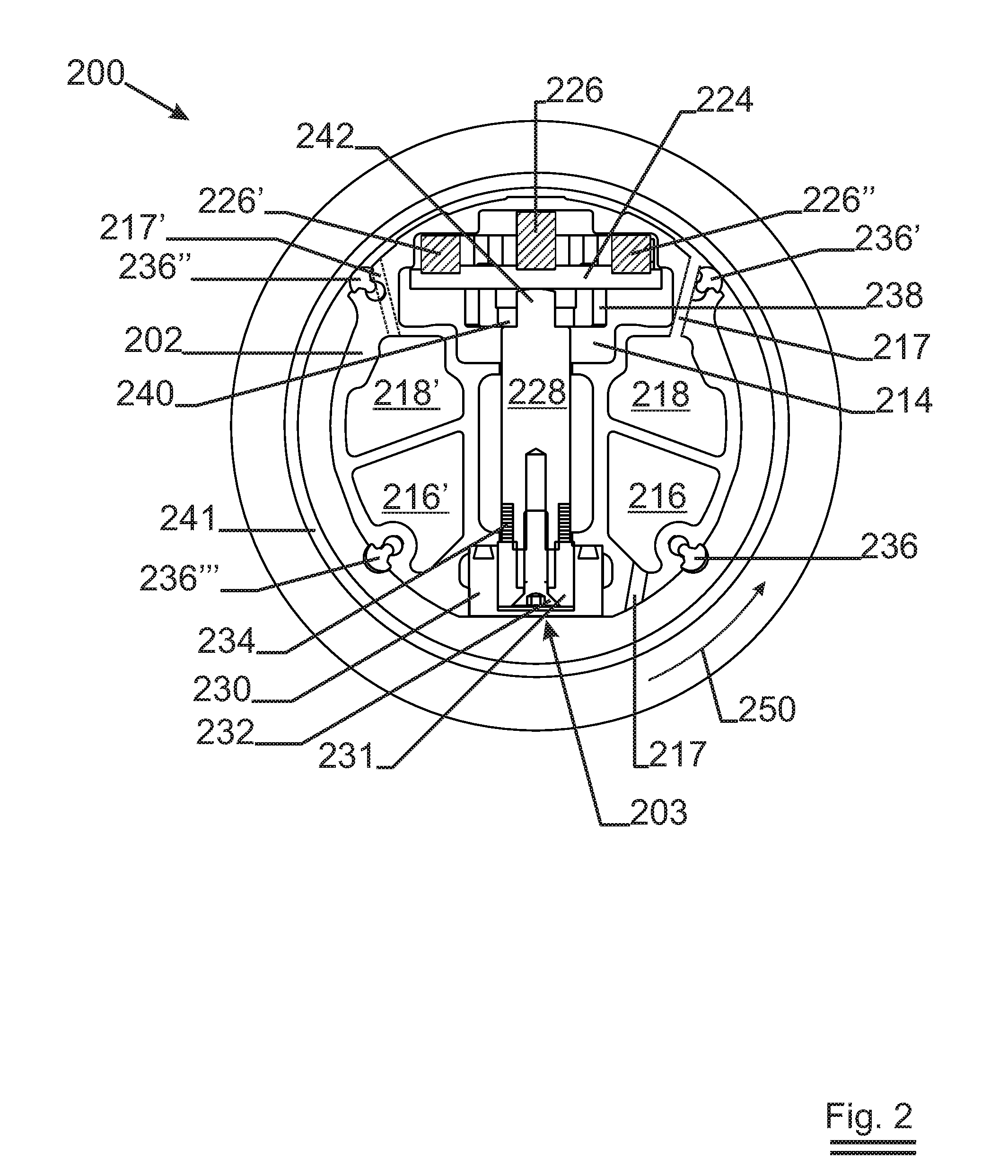
[0031]The adjustment mechanism to change the distance between outer tube wall and generator can be diverse, from simple to more complex. Mechanical systems are straightforward. The simplest is to introduce shims or washers over a screw that holds the support in place to increase the overall length of the support. Another is to introduce an adjustment screw in the support where the screw turns in a threading fixedly connected to the tube while the end of the screw is axially held by a holder connected to the generator in which it can freely turn. Alternatively, the threading in the support can be fixed to the generator, while the screw turns without displacement in a holder connected to the tube. The latter is preferred because the screw protrusions outside the tube do not change upon adjustment. Another possibility is wedge sliders that transform a large linear movement in one direction into a small but accurate displacement perpendicular to the movement.
[0043]In order to prevent the formation of still coolant zones where the coolant does not move, some turbulence can be induced in the flow of coolant between the target and the tube. This can be achieved by giving the outer surface of the tube a corrugated shape. The turbulence also results in better mixing of the coolant.
[0049]A rotatable target comprises a target tube made of a non-magnetic material such as stainless steel and target material disposed thereon. The above invention brings with it a completely new and inventive rotatable target design wherein the target tube wall can be much thinner than the currently used heavy target tubes with wall thicknesses of 4 mm and more. Such target tubes readily have stiffnesses in excess of 700 GNmm2. Indeed the combination of wall thickness and the material used for the target tube may allow stiffness of the target tubes below 600 GNmm2, or even below 500 GNmm2. The target tube wall can then be thinner than 3.8 mm e.g. 3.5 mm or 3.0 mm or even as thin as 2 mm for lengths of 1 meter or more. If the target is shorter than 1 meter, the thickness can even be reduced to 1 mm.
[0052]Thermal stresses will decrease because due to the thin wall of the tube, the tube will yield more easily to the heat extension of the target material. Thick wall tubes resist more this thermal expansion leading to either extreme compressive stresses in the target material (leading to cracking) or delamination of the target material from the target tube.

Problems solved by technology

It remains an engineering challenge when one wants to use cylindrical, rotating targets instead of the easier to implement planar stationary targets.
One of the engineering problems one is faced with is that the magnetic field generator must be contained in the target.
Unfortunately, the magnetic induction (in tesla) of this component normally drops with at least the second power of the distance to its generator and hence is very sensitive to the position of the magnetic field generator with respect to the target surface.
The distance between the target surface and the magnetic field generator must therefore be well controlled as otherwise the plasma would show local variations in intensity that in their turn can lead to non-uniform coating profiles across the substrate.
This heat must be carried away efficiently, as otherwise the target would heat up too much and the magnets of the field generator would loose their strength at higher temperatures leading to a ‘cooling problem’.
Unfortunately, the high performance magnets tend to corrode very fast and therefore they must be sealed from the coolant (‘the sealing problem’)
The disadvantage of this approach is that the coolant gets hotter and hotter as it nears the one end and hence leads to a gradient in temperature on the target and the magnet that on its turn leads to a gradient in deposition rate.
However, neither the magnet array is sealed from the coolant nor are adjustment devices provided to adapt the magnetic field.
The use of this magnetron is limited to smaller scale installations.

Method used


Image

  • Rotatable sputtering magnetron with high stiffness
  • Rotatable sputtering magnetron with high stiffness
  • Rotatable sputtering magnetron with high stiffness

Examples


Embodiment Construction

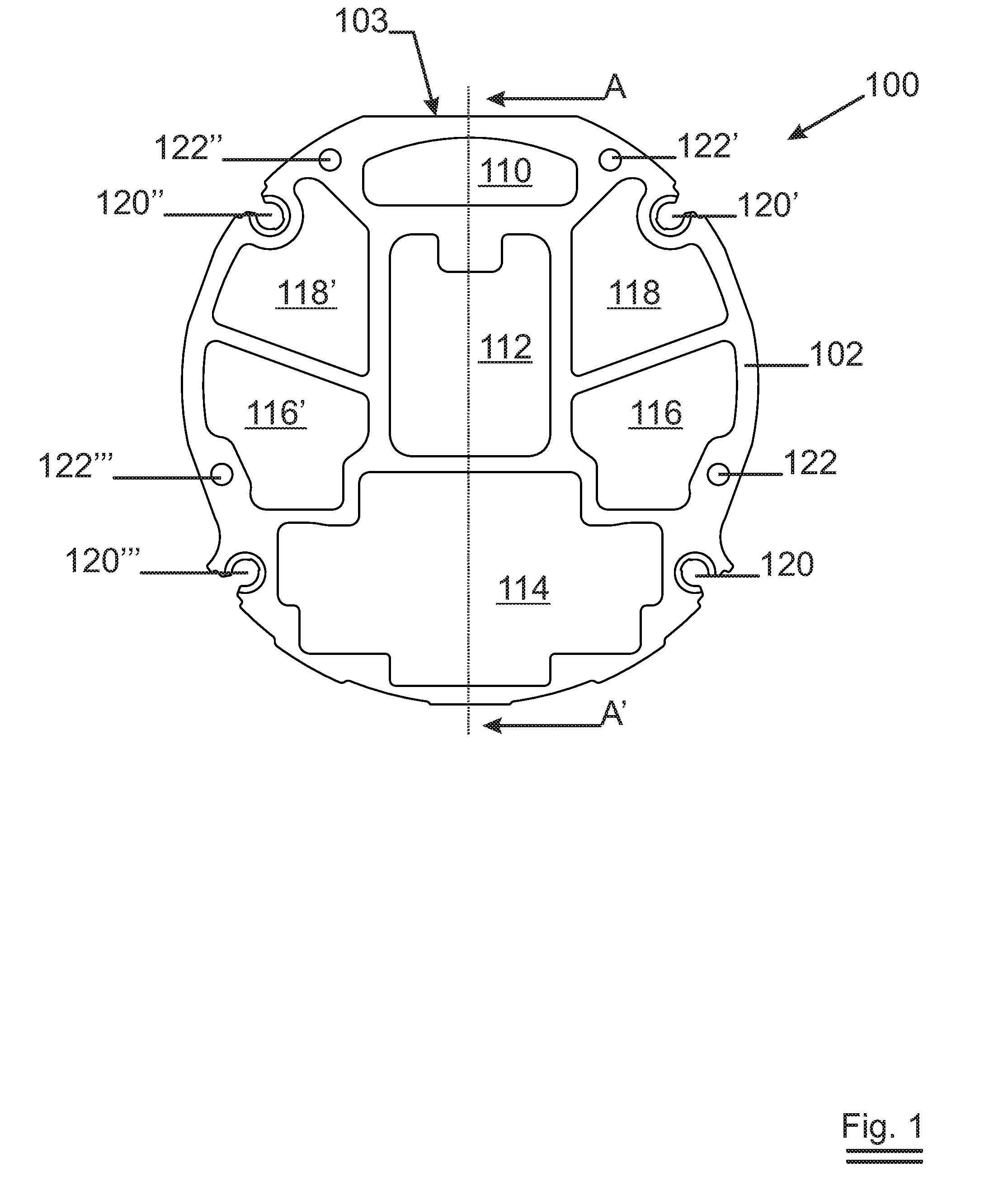
[0061]FIG. 1 is a cross section of the tube 100 showing the extruded multi-walled tube of Duraluminium 102 which is in one single piece of material. In this particular embodiment the diameter of the tube is about 115 mm which fits into the interior of a 125 inner diameter target tube. Different compartments can be discerned that extend over the whole length of the magnetron tube: 114 will accommodate the magnet generator, 110 the adjustment mechanism for the supports. 112 will hold the support themselves. Compartments 118, 118′, 116, 116′ can be used for other purposes such as feeding and extraction of coolant, feed trough of tubing, cables or the like. The holes 122, 122′, 122″, 122′″ are threaded holes (not extending over the entire length of the tube, only at either end of the tube) for receiving screws to fix the closure pieces (not shown). The tube is to be mounted such that bending occurs in the plane AA′.

[0062]When calculating the stiffness of the tube compared to the prior-a...


PUM

PropertyMeasurementUnit
Thicknessaaaaaaaaaa
Thicknessaaaaaaaaaa
Volumeaaaaaaaaaa

Abstract

A sputtering magnetron (300) insertable in a rotatable target is described. The magnetron is designed around a single piece, multiwalled tube (102, 202) with compartments (316, 316′, 318, 318′) extending over the length of the tube. The multiwalled tube gives a much stiffer magnetron carrier structure compared to prior art magnetrons. As a result, the magnetic field generator can be mounted inside a compartment and the distance between magnets and target surface is easily adjustable as the tube is much stiffer than the generator. Additionally, the coolant channels can be incorporated inside the tube and close to the outer wall of the tube so that coolant can be supplied in the vicinity of the magnetic field generator. The increased stiffness of the magnetron allows the target tube to be carried by the magnetron—not the other way around—at least during part of the useful life of the target. As a result thin target carrier tubes can be used as they don't have to carry the magnetron anymore resulting in a longer use of the target.

Description

TECHNICAL FIELD[0001]The invention relates to sputtering magnetrons as used with rotatable targets in apparatus for coating large areas such as display coaters, large area glass coaters, web coaters or a similar kind of equipment.BACKGROUND ART[0002]Physical vapour deposition by means of sputtering has become a standard technique to customise the properties of glass panes or other transparent materials. ‘Sputtering’ refers to the ballistic ejection of coating material atoms out of a target by means of positively charged ions of a heavy noble gas—usually argon—that are accelerated by an electric field towards a negatively charged target. The positive ions are formed by impact ionisation in the low pressure gas phase. The ejected atoms impinge with high kinetic energy on the substrate to be coated where they form a dense, well adhering coating.[0003]The ionisation of the noble gas is confined close to the surface of the target by means of a magnetic field generated from within the tar...

Claims


Application Information

Patent Timeline
IPC IPC(8): C23C14/35
CPCH01J37/3405H01J37/3497H01J37/3435H01J37/342
Inventor GODERIS, PARSIFALVAN DE PUTTE, IVAN
Owner SOLERAS ADVANCED COATINGS NV
Learn More