Electrical terminal connection with molded seal

a technology of electrical terminals and seals, applied in the direction of connection contact materials, dustproof/splashproof/drip-proof/waterproof/flameproof connections, coupling device connections, etc., can solve the problems of terminals producing galvanic corrosion of aluminum at the interface, galvanic reaction corroding aluminum, etc., to achieve the effect of enhancing sealing performance and suppressing the length of the outer cover

Inactive Publication Date: 2011-03-24
APTIV TECH LTD
View PDF9 Cites 45 Cited by
  • Summary
  • Abstract
  • Description
  • Claims
  • Application Information

AI Technical Summary

Benefits of technology

[0010]In accordance with yet another embodiment of the invention, the electrical connection structure further includes a connector housing that defines a cavity having an opening, the cavity receiving the exposed lead and the core crimp wings, the outer cover extending from an axial end at the exposed lead through the opening, the molded hot melt seal entirely surrounding a length of the outer cover that extends from the axial end to a location on the cover spaced a distance apart from the housing. The hot melt seal suppresses flexing of the length of the outer cover. Such an embodiment is advantageous for providing strain relief and enhancing sealing performance in applications where the cable is subject to flexing forces outside the housing.

Problems solved by technology

However, copper and copper based alloys are relatively expensive and are also heavy.
The crimp interface connection of aluminum based cable to a copper based terminal can produce a galvanic corrosion of the aluminum at the interface, if an electrolyte, for example salt water, is present.
The galvanic reaction corrodes the aluminum because the aluminum or aluminum alloy has a different galvanic potential than the copper or copper alloys of the terminals.
However, grease has been shown to be an ineffective preventative in the long term under harsh automotive environments where salt sprays and water pressures can easily wear away at the grease and expose the crimp interface.
In the case of an aluminum and copper interface, even a small amount of exposed aluminum cable can contribute to significant galvanic corrosion.

Method used


Image

  • Electrical terminal connection with molded seal
  • Electrical terminal connection with molded seal
  • Electrical terminal connection with molded seal

Examples


Embodiment Construction

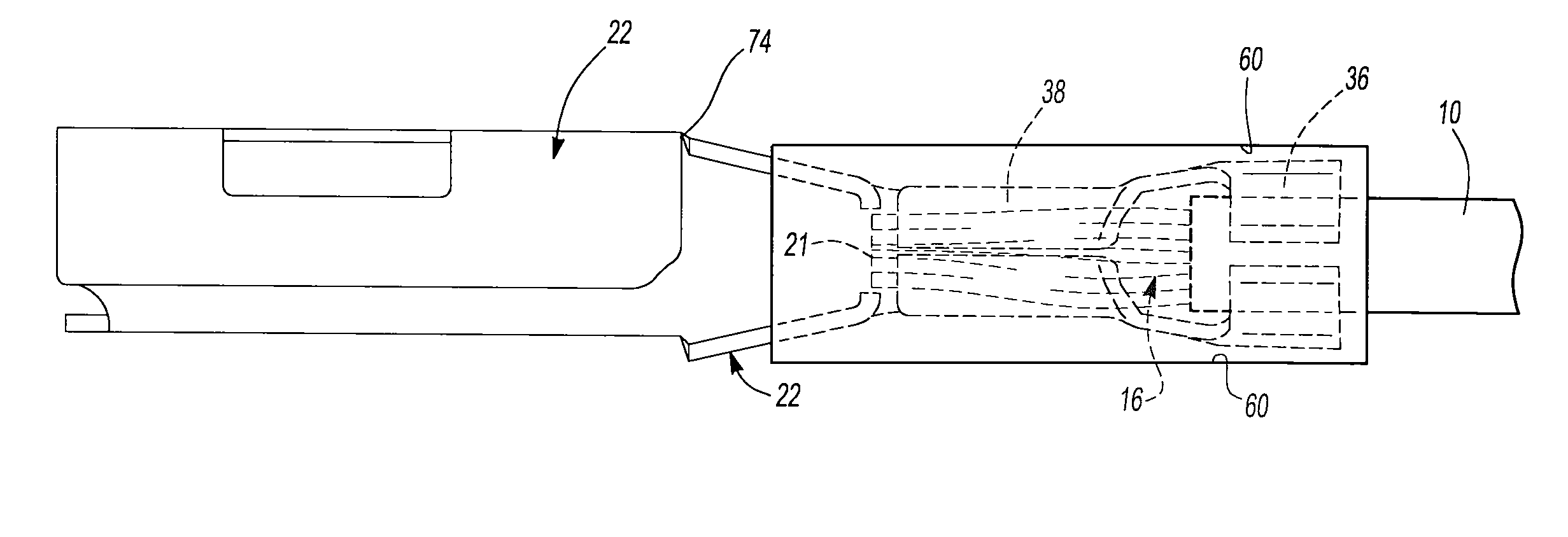
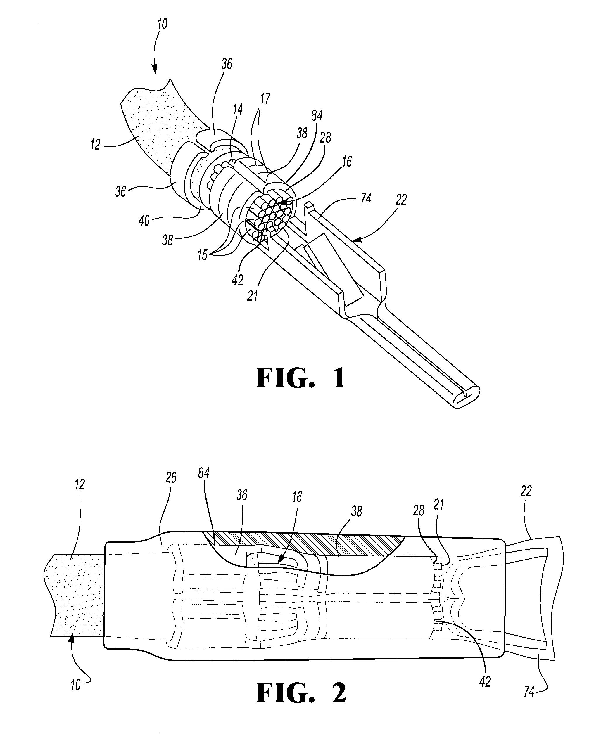
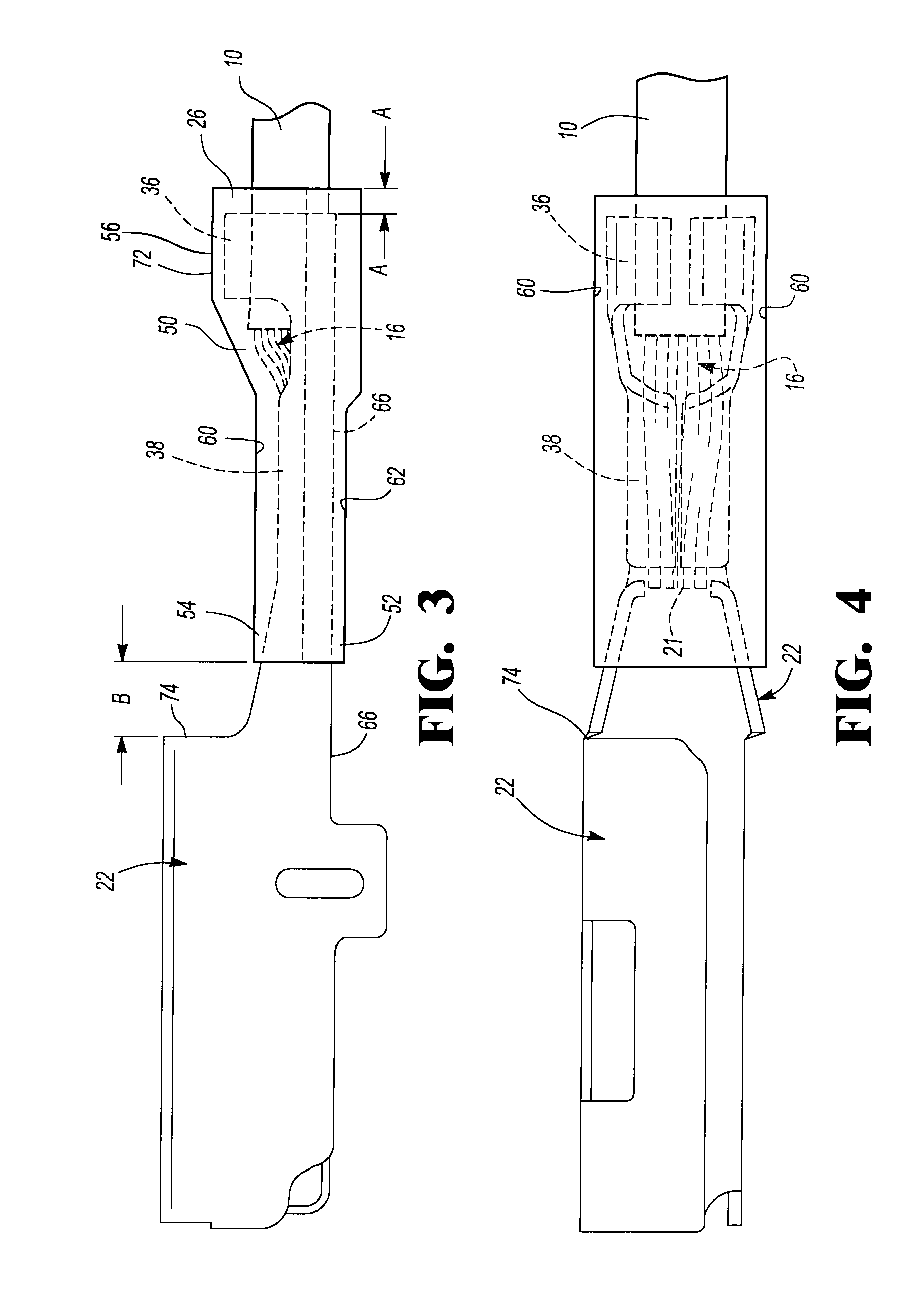
[0026]Referring to FIG. 1, an exemplary embodiment of the invention includes a cable 10 having an insulative outer cover 12 and an aluminum based core 14. Core 14 is made of a plurality of individual strands 15 bundled and twisted together. An end portion of insulative outer cover 12 is removed to expose a lead 16 of core 14. A terminal 22 made from a copper alloy has a rearward portion 84 including a pair of insulation crimp wings 36 and a pair of core crimp wings 38 with a notch or gap 40 therebetween. Wings 36 and 38 are crimped onto cable 10 such that terminal 22 is secured to insulative outer cover 12 and makes electrical contact with lead 16 of core 14. Voids 42 are formed between individual strands 15 of core 14 after terminal 22 is crimped onto cable 10. Core crimp wings 38 may optionally include serrations 17 to improve the bite of core crimp wings 38 into aluminum lead 16.

[0027]Referring now to FIG. 2, a hot melt seal 26 is then molded about terminal 22 and cable 10 and it...


PUM

PropertyMeasurementUnit
distanceaaaaaaaaaa
heightaaaaaaaaaa
thicknessaaaaaaaaaa

Abstract

A corrosion resistant electrical connection structure has an electrically conductive cable with an electrically conductive core and an insulative outer cover. An electrically conductive terminal is electrically connected to a lead of the core that extends beyond the insulative outer cover. A molded hot melt seal seals the lead of the core and the terminal interface section from ambient electrolytes. In an exemplary embodiment, the core is made from aluminum or an aluminum alloy and the terminal is made from a copper alloy.

Description

PRIORITY[0001]The application claims the benefit of U.S. provisional patent application Ser. No. 61 / 243690, filed Sep. 18, 2009, which is hereby incorporated by reference.TECHNICAL FIELD[0002]The field of this invention relates to an electrical connection between a cable and a terminal with a molded seal to reduce corrosion.BACKGROUND OF THE DISCLOSURE[0003]Insulated copper based cable is commonly used for automotive wiring. Copper has high conductivity, good corrosion resistance and adequate mechanical strength. However, copper and copper based alloys are relatively expensive and are also heavy.[0004]Interest in weight savings and cost savings in automotive electrical wiring applications have made aluminum based cables an attractive alternative to copper based cables. However, some wiring and electrical connectors may remain copper based. Thus, there may be a transition somewhere in the electrical circuit between an aluminum based portion of the circuit and a copper based portion o...

Claims


Application Information

Patent Timeline
Patent Type & Authority Applications(United States)
IPC IPC(8): H01R13/52B29C65/56B29C65/70B29C65/72
CPCH01R4/62H01R4/70H01R13/5216Y10T156/1005H01R4/185H01R13/5208H01R43/24H01R43/005H01R4/18H01R11/12
Inventor SAKAI, ATSUSHI
Owner APTIV TECH LTD
Why Eureka
Try Eureka