Apparatus and method for manufacturing vitreous silica crucible

Active Publication Date: 2011-04-07
SUMCO CORP
View PDF20 Cites 10 Cited by
  • Summary
  • Abstract
  • Description
  • Claims
  • Application Information

AI Technical Summary

Benefits of technology

According to the above-mentioned configurations of the present invention where the amount of fume generation is measured during manufacturing a vitreous silica crucible, it is possible to prevent fumes to attach to a silica powder layer in the manufacturing process, and real-time control of raw material melting state is enabled. Therefore, ununiformity of product proper

Problems solved by technology

However, in any of the above-mentioned documents, the amount of fumes generated in the manufacturing process of a vitreous silica crucible was not precisely detected, and fumes were removed in a post-process.
Thus, proper control of the manufacturing condition was difficult.
Therefore, the methods in the above-mentioned documents cannot improve an inner surface property, and thus cannot improve productivity and a yield.
Especially, contact temperature measurement of a melted portion is not preferred because contamination can occur and measurement element (terminal) can be damaged by high temperature of arc plasm

Method used


Image

  • Apparatus and method for manufacturing vitreous silica crucible
  • Apparatus and method for manufacturing vitreous silica crucible
  • Apparatus and method for manufacturing vitreous silica crucible

Examples


example

Hereinafter, the apparatus and the method of manufacturing a vitreous silica crucible will be explained in detail with reference to Examples. The present invention is not limited to the Examples.

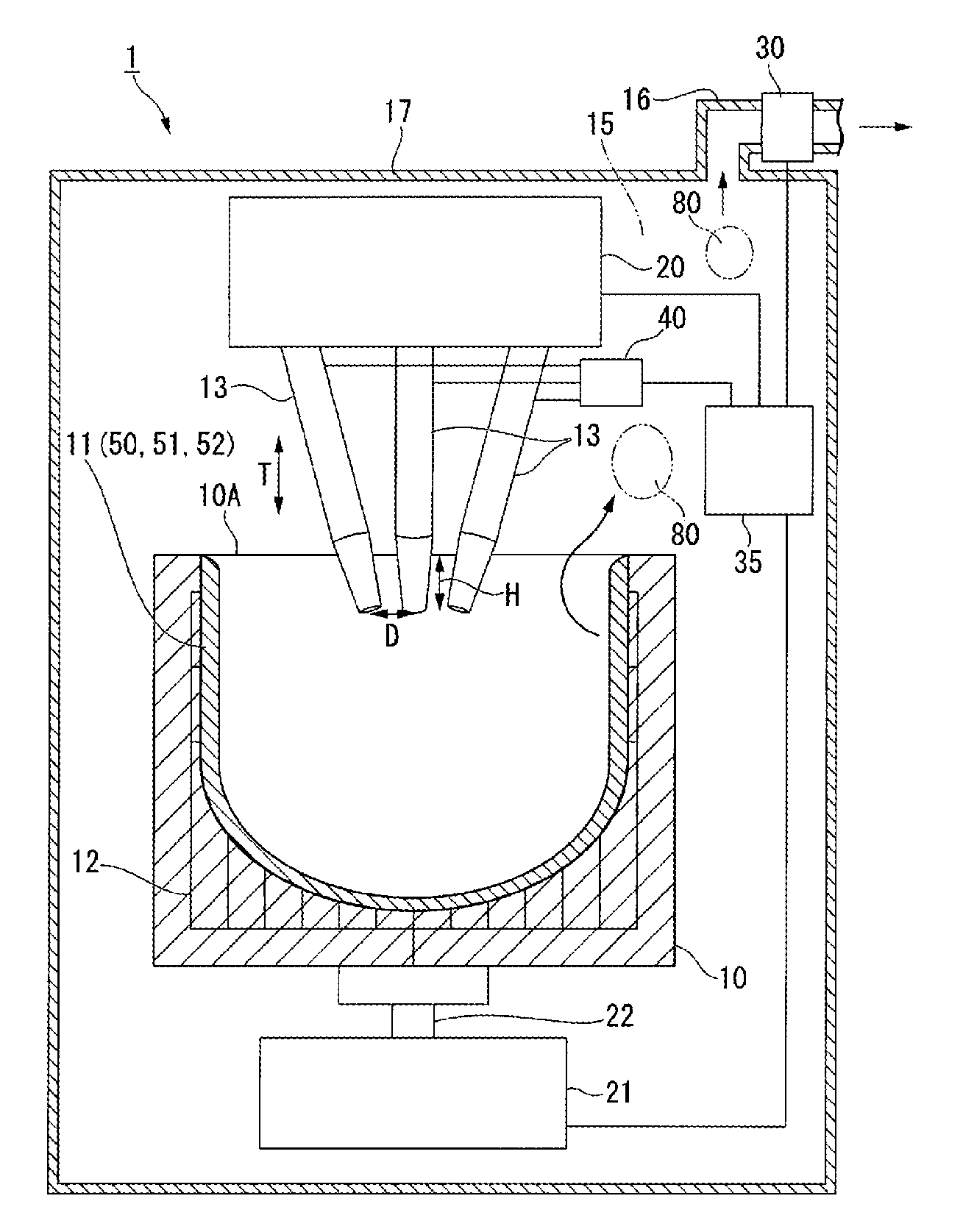
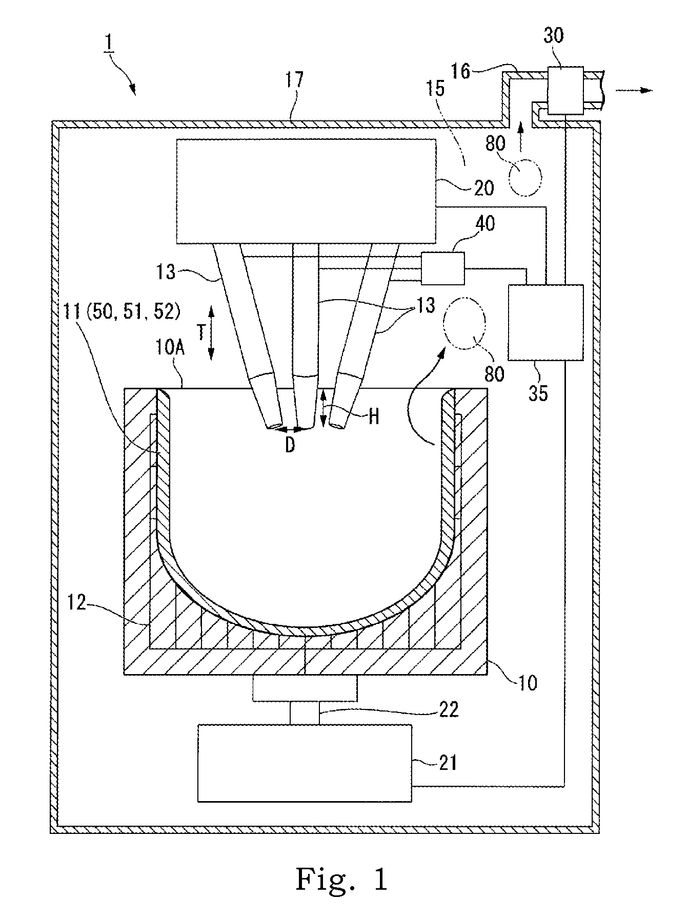
In each of the following Examples and Comparative examples, a vitreous silica crucible was manufactured by the rotating mold method under the conditions described below. The mold had an opening diameter of 868.8 mm (34.2 inches), an average thickness of a silica powder layer deposited on the mold inner surface was 28 mm to manufacture a vitreous silica crucible with an opening diameter of 812.8 mm (32 inches). The electrodes were powered for 60 minutes to melt the silica powder layer, and likewise vacuum suction of the silica powder layer was conducted for the 60 minutes from the beginning in a pressure of at most approx. 80 to 90 to 100 to 120 kPa by a pressure-reducing unit.

examples 1 to 6

In Examples 1 to 3, used was an apparatus for manufacturing a vitreous silica crucible including a fume-amount measurement unit on an outlet tube having an opening to a furnace inside in a position 10 cm above an upper end of the mold. The outlet tube was connected to the outside of the furnace. A silica powder layer deposited on the mold inner surface was melted to be vitrified while detecting the amount of fumes generated in the mold. A photosensor, a CCD camera which was an imaging unit, or a dielectric sensor was used as a fume-amount measurement unit. A fume-amount measurement unit which was capable of arithmetic processing image signals is used. Arc discharge was conducted under the conditions shown in Table 1 to manufacture vitreous silica crucibles of Examples 1 to 3. In Table 1, the location of the fume-amount measurement unit was described as “furnace inside.”

In a similar manner to Examples 1 to 3, in Examples 4 to 6, used was an apparatus for manufacturing a vitreous sili...


PUM

PropertyMeasurementUnit
Fractionaaaaaaaaaa
Timeaaaaaaaaaa
Areaaaaaaaaaaa

Abstract

Provided are an apparatus and a method for manufacturing a vitreous silica crucible, which enable accurate measurement of a fume generation amount, prevention of deterioration of an inner surface property, and real-time control of a raw material melting state. Provided is an apparatus for manufacturing a vitreous silica crucible 50 by supplying silica powder into a mold 10 to form a silica powder layer 11, and heating and melting the silica powder layer 11 by arc discharge. The apparatus includes the mold 10 for defining an outer shape of a vitreous silica crucible, an arc discharge unit having a plurality of carbon electrodes 13 and a power-supply unit 40, and a fume-amount measurement unit 30 for detecting an amount of fumes 80 generated in the mold 10.

Description

CROSS-REFERENCE TO RELATED APPLICATIONThis application is related to Japanese Patent Applications No. 2009-230832 filed on Oct. 2, 2009 and No. 2010-204464 filed on Sep. 13, 2010, whose priorities are claimed, and the disclosures of which are incorporated by reference in their entirety.BACKGROUND OF THE INVENTION1. Field of the InventionThe present invention relates to an apparatus and a method for manufacturing a vitreous silica crucible, and more specifically relates to a technique appropriate for inner surface property control in manufacturing a vitreous silica crucible for pulling a silicon single crystal.2. Description of Related ArtIn general, a silicon single crystal has been manufactured by the Czochralski method (the CZ method) using a vitreous silica crucible. In this method, polycrystalline silicon raw material is charged into a vitreous silica crucible, the raw material is melted to form silicon melt, a seed crystal is dipped into the silicon melt and the seed crystal is...

Claims


Application Information

Patent Timeline
IPC IPC(8): C03B20/00C03B19/09
CPCC30B15/10C03B19/095Y02P40/57
Inventor SUZUKI, ERIKOKISHI, HIROSHI
Owner SUMCO CORP
Why Eureka
Try Eureka