Internal combustion engine and supercharger

a supercharger and internal combustion technology, applied in liquid fuel engines, machines/engines, electric control, etc., can solve the problems of internal cooling of the supercharger components and the lower air discharge temperature of compressed air delivered to the engine, so as to improve the power-to-weight ratio of the engine, increase the flow rate, and improve the effect of engine speed

Inactive Publication Date: 2011-04-14
HANSEN ENGINE
View PDF64 Cites 18 Cited by
  • Summary
  • Abstract
  • Description
  • Claims
  • Application Information

AI Technical Summary

Benefits of technology

[0012]The invention comprises an internal combustion engine having an air intake manifold accommodating air near or above atmospheric pressure operably connected to a load, such as a motor vehicle drive system, pump or an electric generator, combined with a variable internal compression ratio and air flow rate supercharger for supplying varying amounts of air to the engine. Examples of this internal combustion engine are a diesel engine or a spark-assisted engine. Other engines that generally operate without throttled intake manifolds hereinafter referred to as diesel-like engines are further examples of the internal combustion engines of this invention. The supercharger in a first operation or case has the rate of air flow delivered to the engine matched with the rate of air flow drawn by the engine so that no air pressure rise occurs in the air intake manifold of the engine when naturally aspirated power output of the engine is adequate to meet the load requirement of the engine. In a second operation or case of the supercharger, a proportional amount of air is compressed to a matching air pressure and introduced to the engine's boosted intake manifold. This results in the most efficient operation of the engine from no boost to varying levels of boost. The supercharger is a positive air displacement mechanism or gas compressor powered by the engine to improve the power to weight ratio of the engine. Other power devices, such as electric motors, can operate the air displacement mechanism. The gas compressor is operable to move gas selectively, a first portion of the gas to a first location and a second portion of the gas to a second location. In the case of constant speed application, the supercharger has an air flow control that regulates the volume and pressure of air compressed by the supercharger to the engine to maintain the speed of the engine substantially constant when driving variable loads better than a smaller displacement engine could without the supercharger. The supercharger operates to increase the flow of the air to the cylinders of the engine responsive to the power requirements of the engine improving the engine's overall efficiency. Air is moved through the supercharger with a pair of rotating screws or rotors or one female and one male rotor having cooperating helical grooves and protrusions or lands that create positive air flow to the engine. The twin rotors are a durable part of or component of a compact and efficient air compressor that delivers air to the engine to achieve the performance required by the engine. The volume of air flow discharged by the supercharger is regulated by controlling the effective air trapping length of the twin rotors. One or more slide assemblies associated with the rotors control the air moving and compressing operation of the supercharger. The air flow control is a movable slide assembly in one embodiment of the supercharger comprising an elongated slide or member movably positioned adjacent one side of a rotor to regulate the amount of air trapped by the rotating rotors and to vent excess air to atmosphere thereby cooling the rotors and adjacent housing and increasing the pumping efficiency of the supercharger. An actuator connected to the member functions to move the member between maximum air bypass, partially air bypass and minimum air bypass positions relative to the rotors. When the member is in the maximum air bypass position, only the naturally aspirated volume of air is pump

Problems solved by technology

In this case, the excess air discharged to atmosphere results in internal cooling of the superc

Method used


Image

  • Internal combustion engine and supercharger
  • Internal combustion engine and supercharger
  • Internal combustion engine and supercharger

Examples


Embodiment Construction

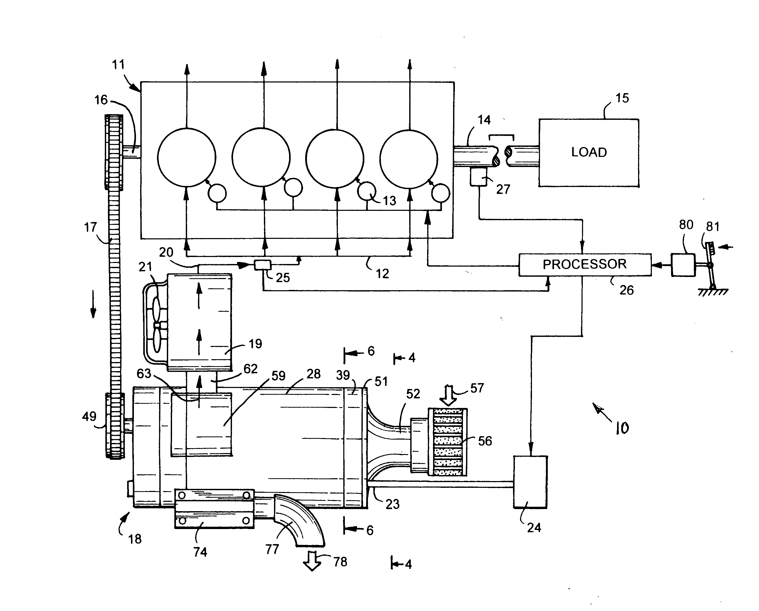
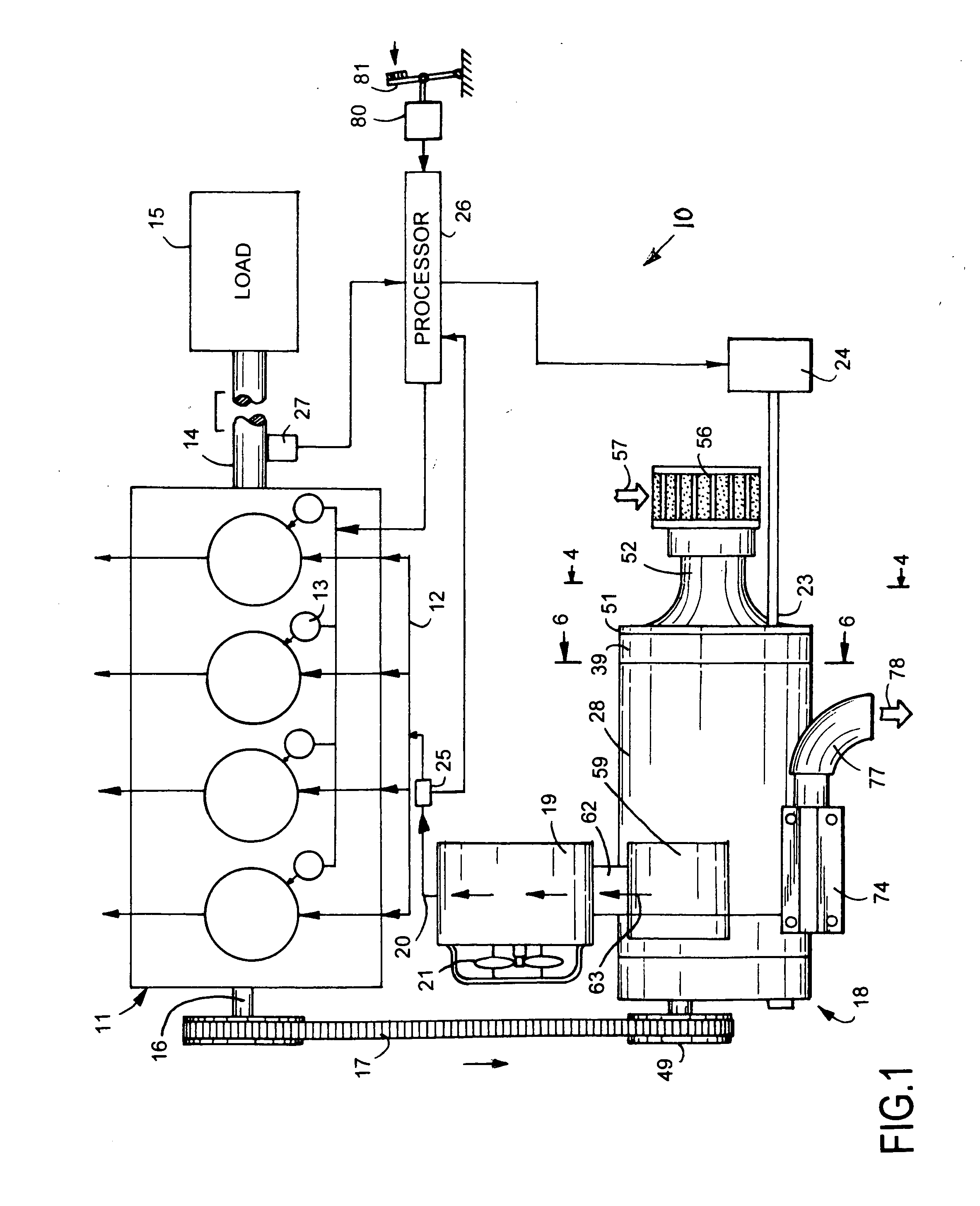
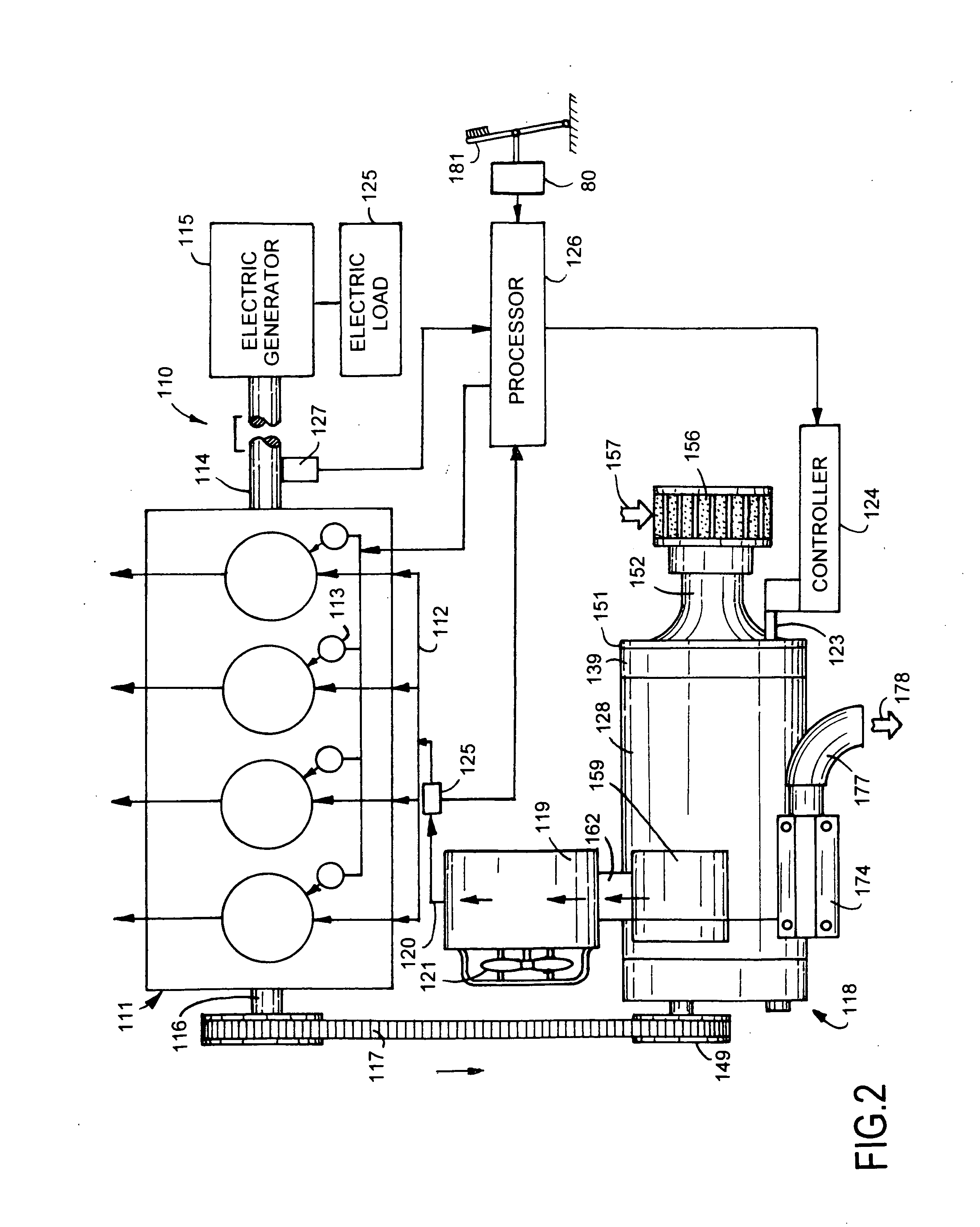
[0035]The supercharged internal combustion power unit 10, shown in FIG. 1, is an internal combustion engine 11 having an air intake manifold 12 and a drive shaft 14 operably connected to a load 15. Engine 11 is an air compression ignition internal combustion engine, such as a conventional diesel internal combustion engine, with fuel injectors 13 operable to timely introduce fuel into the engine's combustion chambers. Engine 11 is an internal combustion engine typically using the heat of compressed air to initiate ignition to burn fuel injected into the engine's combustion chambers during the final stage of air compression. Engine 11 includes air compression spark assisted engines and engines that operate near or above atmospheric air pressure in the engine's air intake manifold. These engines are herein referred to as diesel-like engines. Load 15 can be a motor vehicle drive system, a pump, an electric generator or machines drivably coupled to drive shaft 14. A front drive shaft 16 ...


PUM


Abstract

A diesel or diesel-like internal combustion engine drivably connected to a variable internal compression ratio supercharger that supplies varying amounts of air to the engine responsive to the load requirements of the engine. The supercharger has a pair of rotors concurrently driven by the engine to move air to the engine. A slide assembly associated with screw rotors is movable with a controller relative to the rotors to bypass air to atmosphere and regulate the amount of air and pressure of the air compressed by the screw rotors to the engine to increase the engine's efficiency.

Description

CROSS REFERENCE TO RELATED APPLICATION[0001](None.)FIELD OF THE INVENTION[0002]The technology of the invention relates to internal combustion engines equipped with superchargers for supplying air to the engines according to the requirements of the engines to increase efficiency and performance of the engines.BACKGROUND OF THE INVENTION[0003]Air displacement devices have been developed and used to increase the supply of air and fuel to internal combustion engines to boost engine horsepower. An example of an air displacement device is the “Roots blower” shown by P. H. Roots in U.S. Pat. No. 30,157 and G. Scheerer in U.S. Pat. No. 2,201,014. Each of these devices has a belt-driven shaft that drives two close-clearance rotors. The rotating rotors during each rotation sweep out a specific volume of air to an air receiver, such as an internal combustion engine. The rotational speed of the rotors largely determines the unthrottled volume of air discharged by the device.[0004]C. N. Hansen a...

Claims


Application Information

Patent Timeline
IPC IPC(8): F02D23/00F02B33/00
CPCF01C11/008F02B33/38F02B33/44F02D23/00Y02T10/17F04C18/16F04C28/12Y02T10/144F02D41/0007Y02T10/12Y02T10/40
Inventor HANSENCROSS, PAUL C.
Owner HANSEN ENGINE
Why Eureka
Try Eureka