
Segregated in-situ forced oxidation wet flue gas desulfurization for oxygen-fired fossil fuel combustion

Active Publication Date: 2011-04-14
THE BABCOCK & WILCOX CO
View PDF9 Cites 21 Cited by
  • Summary
  • Abstract
  • Description
  • Claims
  • Application Information

AI Technical Summary

Benefits of technology

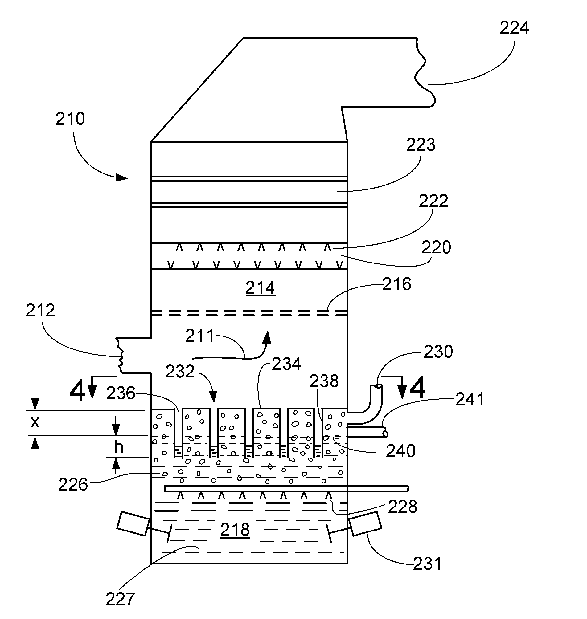
[0008]In accordance with the present invention a perforated wall or division plate both separates and communicates the gas scrubbing zone and the reaction zone of the WFGD tower, whereby absorbent liquid slurry can drain into the reaction zone, but the oxidation air in the reaction zone cannot enter the gas scrubbing zone, thereby preventing the introduction of nitrogen into the flue gas passing through the gas scrubbing zone.
[0010]In accordance with the present invention; a wall separates and communicates the gas scrubbing zone and the reaction zone. The wall prevents the oxidation air in the reaction zone from mixing with the flue gas in the gas scrubbing zone. During operation of the WFGD tower, the gas scrubbing zone is under positive gas pressure, whereas the reaction zone is at atmospheric pressure, therefore, it is preferable for the wall to be seal-welded in gas tight manner to the WFGD tower shell. A nearly gas tight weld is acceptable; however some flue gas will leak into the reaction chamber and be vented with the oxidation air to atmosphere. The wall is structured and arranged to extend into the reaction zone liquid slurry, below a nominal depth required to establish and maintain a liquid slurry seal, thereby precluding the flue gas from entering the reaction zone, while allowing the partially reacted slurry reagent and the scrubbed products to drain from the gas scrubbing zone into the reaction zone.
[0014]In accordance with the present invention there is provided a method for preventing oxidation air from mixing with the flue gas in an in-situ forced oxidation WFGD tower which includes a gas scrubbing zone and a reaction zone located subjacent to the gas scrubbing zone comprising the steps of: separating and communicating the gas scrubbing zone and the reaction zone; supplying a sulfur oxide absorbing reagent to the gas scrubbing zone; draining partially reacted liquid slurry reagent and scrubbed products from the gas scrubbing zone into the reaction zone; maintaining a set slurry level in the reaction zone and agitating the liquid slurry; establishing a liquid slurry seal between the gas scrubbing zone and the reaction zone; introducing oxidation air into the reaction zone to force the in-situ oxidation of sulfur compounds collected in the reaction zone; and venting the oxidation air from the reaction zone to atmosphere.

Problems solved by technology

Acidic gases are known to be hazardous to the environment, such that their emission into the atmosphere is closely regulated by clean air statutes.
Firing with pure oxygen would result in too high a flame temperature, so the mixture is diluted by mixing with recycled flue gas.
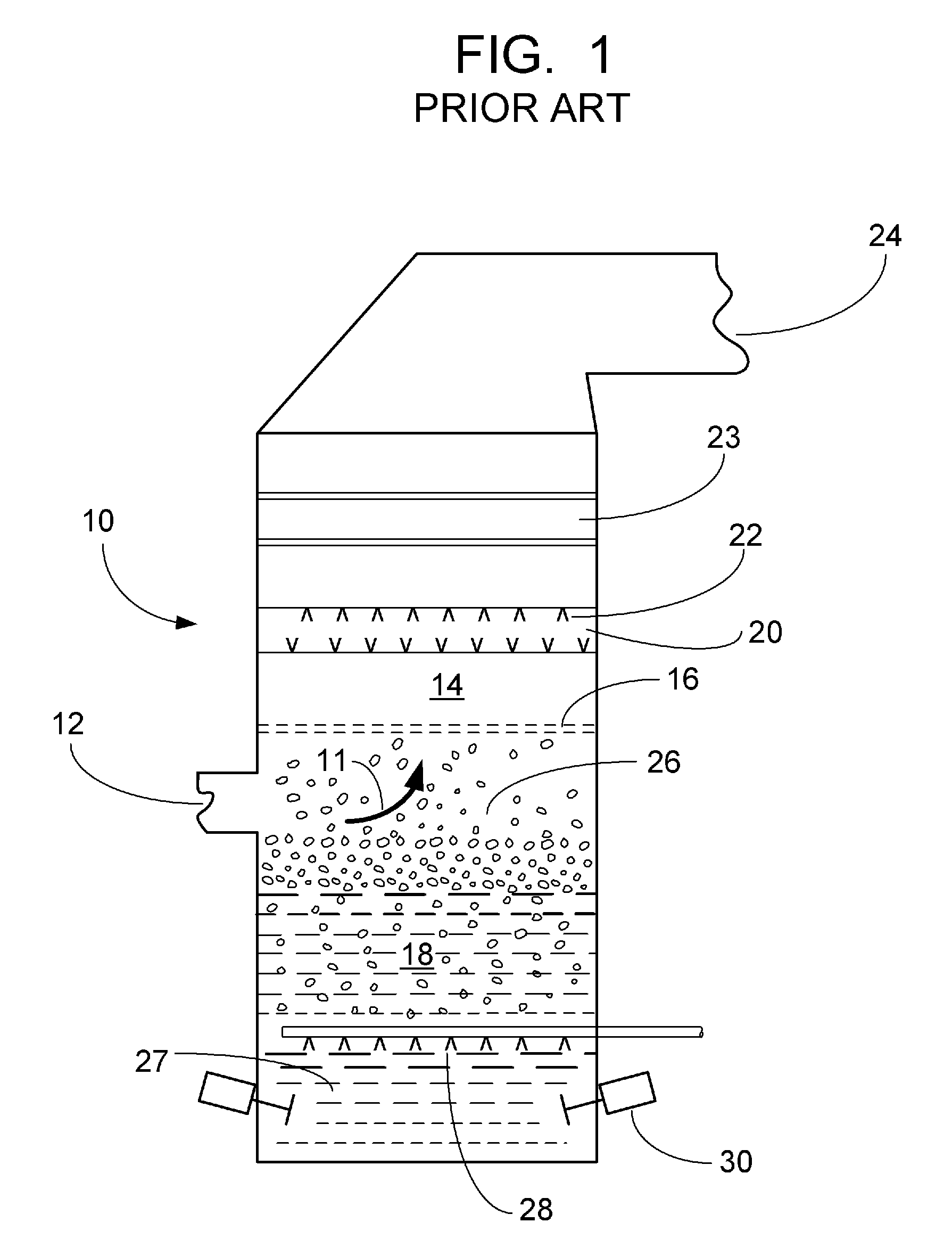
However, at this time, there are no known economically feasible methods or systems for providing in-situ forced oxidation flue gas scrubbing without allowing the oxidation air to enter the gas scrubbing zone, as required in the oxy-fuel combustion process in order to eliminate the introduction of nitrogen in the flue gas stream.

Method used


Image

  • Segregated in-situ forced oxidation wet flue gas desulfurization for oxygen-fired fossil fuel combustion
  • Segregated in-situ forced oxidation wet flue gas desulfurization for oxygen-fired fossil fuel combustion
  • Segregated in-situ forced oxidation wet flue gas desulfurization for oxygen-fired fossil fuel combustion

Examples


Embodiment Construction

[0023]Reference will hereinafter be made to the accompanying drawings wherein like numerals designate the same or functionally similar elements throughout the various figures.

[0024]The present invention resides in preventing the oxidation air in an in-situ forced oxidation WFGD tower from entering the gas scrubbing zone and mixing with the flue gas while allowing the partially reacted reagent and the scrubbed products to drain from the gas scrubbing zone into the reaction zone.

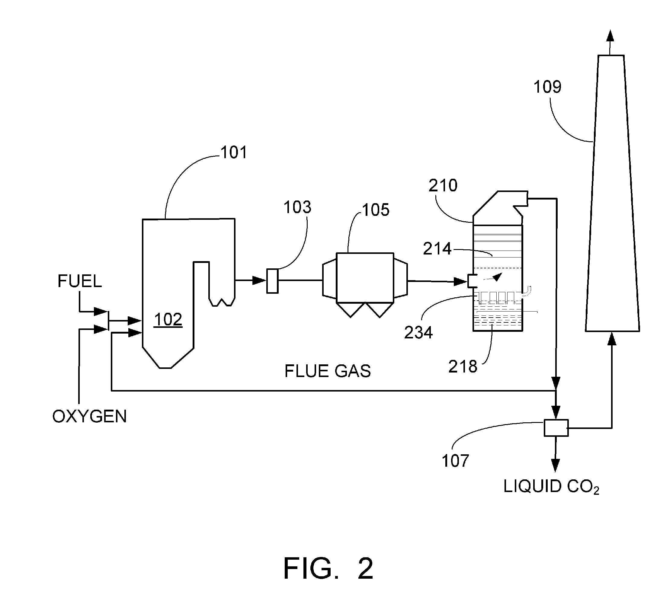
[0025]Referring to FIG. 2, there is shown an oxy-fuel fired system in combination with the in-situ forced oxidation WFGD tower of FIG. 3 by way of illustration only, and the alternative structural embodiments disclosed herein will be readily recognized as viable alternatives that may be employed with an oxy-fuel fired system.

[0026]Turning back to FIG. 2, there is shown, diagrammatically, a segment of a steam electric power plant which is provided with a wet scrubbing installation for treating flue gas in accor...


PUM

PropertyMeasurementUnit
Fractionaaaaaaaaaa
Fractionaaaaaaaaaa
Depthaaaaaaaaaa

Abstract

An in-situ forced oxidation wet flue gas desulfurization apparatus, method and arrangement for utilization with oxy-fuel combustion power plants. The apparatus is a tower-like structure having a flue gas scrubbing zone and a reaction zone located subjacent to the gas scrubbing zone. A sulfur oxide absorbing liquid slurry is supplied to the gas scrubbing zone to react with and scrub the sulfur oxides from the flue gas. The partially reacted liquid slurry reagent and the scrubbed products drain into the reaction zone, rising to a set level. Oxidation air is introduced into the liquid slurry in the reaction zone to force the in-situ oxidation of sulfur compounds collected in the reaction zone. A wall separates and communicates the gas scrubbing zone and the reaction zone, the wall prevents the oxidation air from entering the gas scrubbing zone and extends into the liquid slurry below a nominal depth required to establish and maintain a liquid slurry seal thereby substantially precluding the leakage of flue gas into the reaction zone while allowing the partially reacted liquid slurry reagent and scrubbed products to drain into the reaction zone.

Description

FIELD AND BACKGROUND OF THE INVENTION[0001]The present invention relates, in general, to wet flue gas desulfurization (WFGD) systems and, in particular, to in-situ forced oxidation WFGD scrubber application in oxygen-fired fossil fuel combustion (oxy-fuel combustion).[0002]Air quality laws, both at the federal and state level have set increasingly stringent emission standards. Often of particular concern are sulfur dioxide and other acidic gases produced by the combustion of fossil fuels and various industrial operations. Acidic gases are known to be hazardous to the environment, such that their emission into the atmosphere is closely regulated by clean air statutes.[0003]New technologies are addressing this problem so that fossil fuels and particularly coal can be utilized for future generations without polluting the atmosphere and contributing to global warming. The method by which acidic gases are removed with a gas-liquid contactor or other type of flue gas scrubber is known as ...

Claims


Application Information

Patent Timeline
IPC IPC(8): F23J15/04B01D53/18B01D53/14F23B99/00F23L7/00
CPCB01D53/501B01D53/504B01D53/79B01D53/80B01D2251/11Y02E20/344F23J15/025F23J15/04F23J2215/20F23J2219/50F23J2900/15061F23J15/00Y02E20/34
Inventor MCDONALD, DENNIS K.ROGERS, KEVIN J.
Owner THE BABCOCK & WILCOX CO
Learn More