

Fan with pressurizing structure
- Summary
- Abstract
- Description
- Claims
- Application Information
AI Technical Summary
Benefits of technology
Problems solved by technology
Method used
Image

Examples
first embodiment
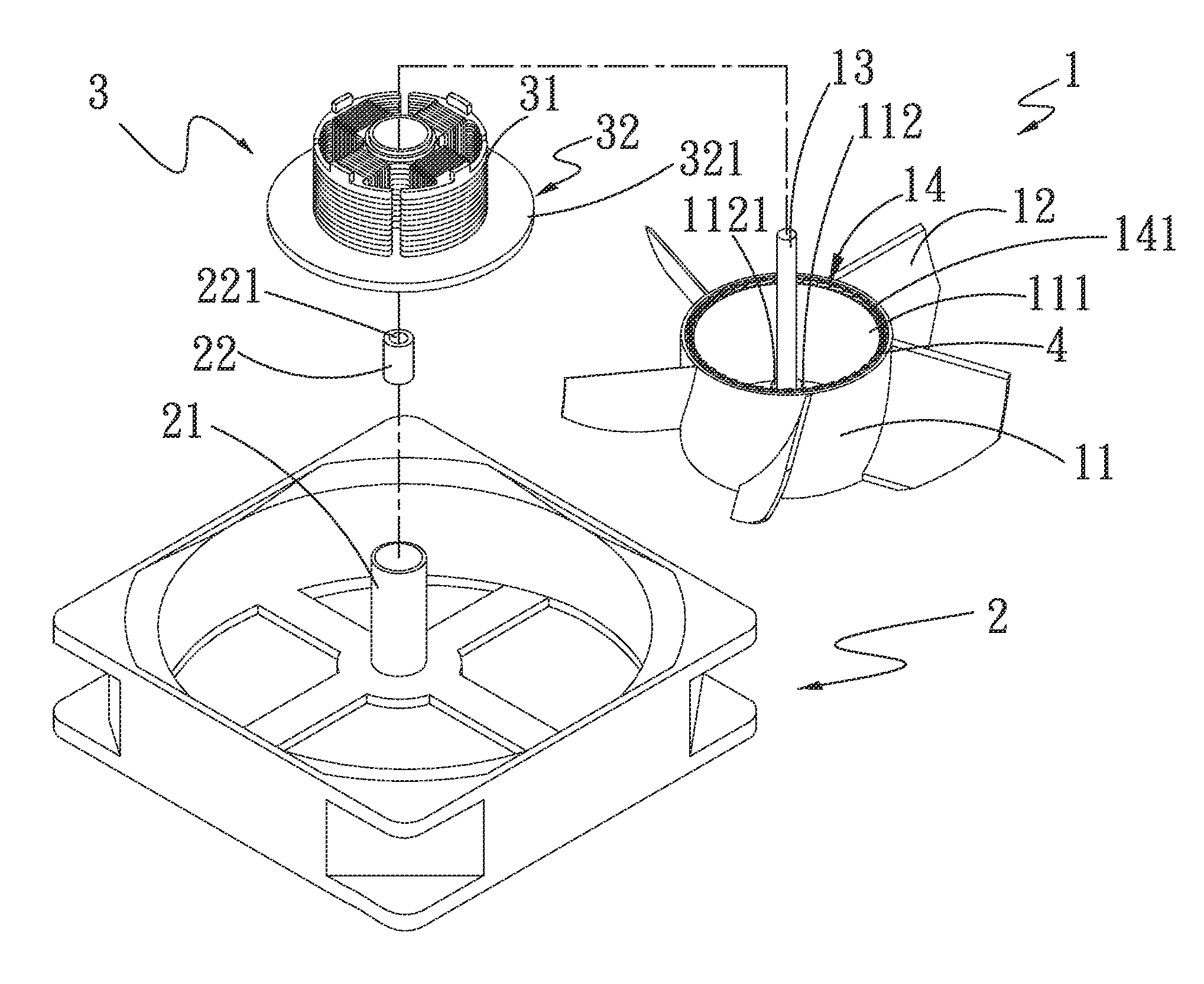
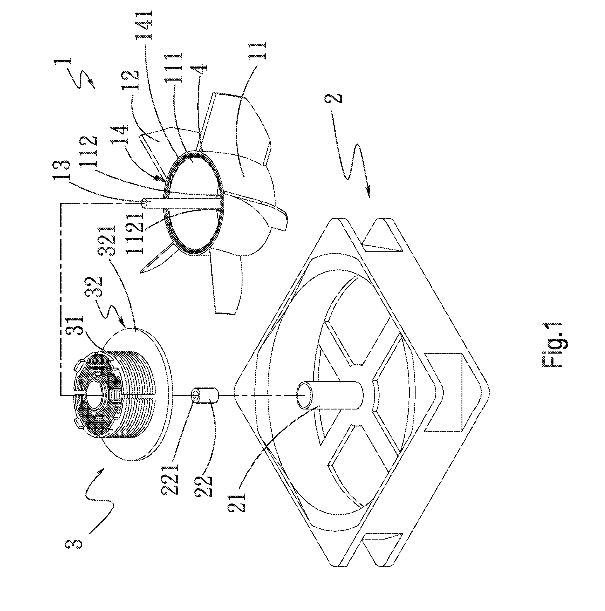
[0023]Please refer to FIGS. 1, 2 and 2a. A fan with pressurizing structure according to the present invention includes a rotor 1, a frame 2, a stator assembly 3, and a plurality of first pressurizing sections 4.
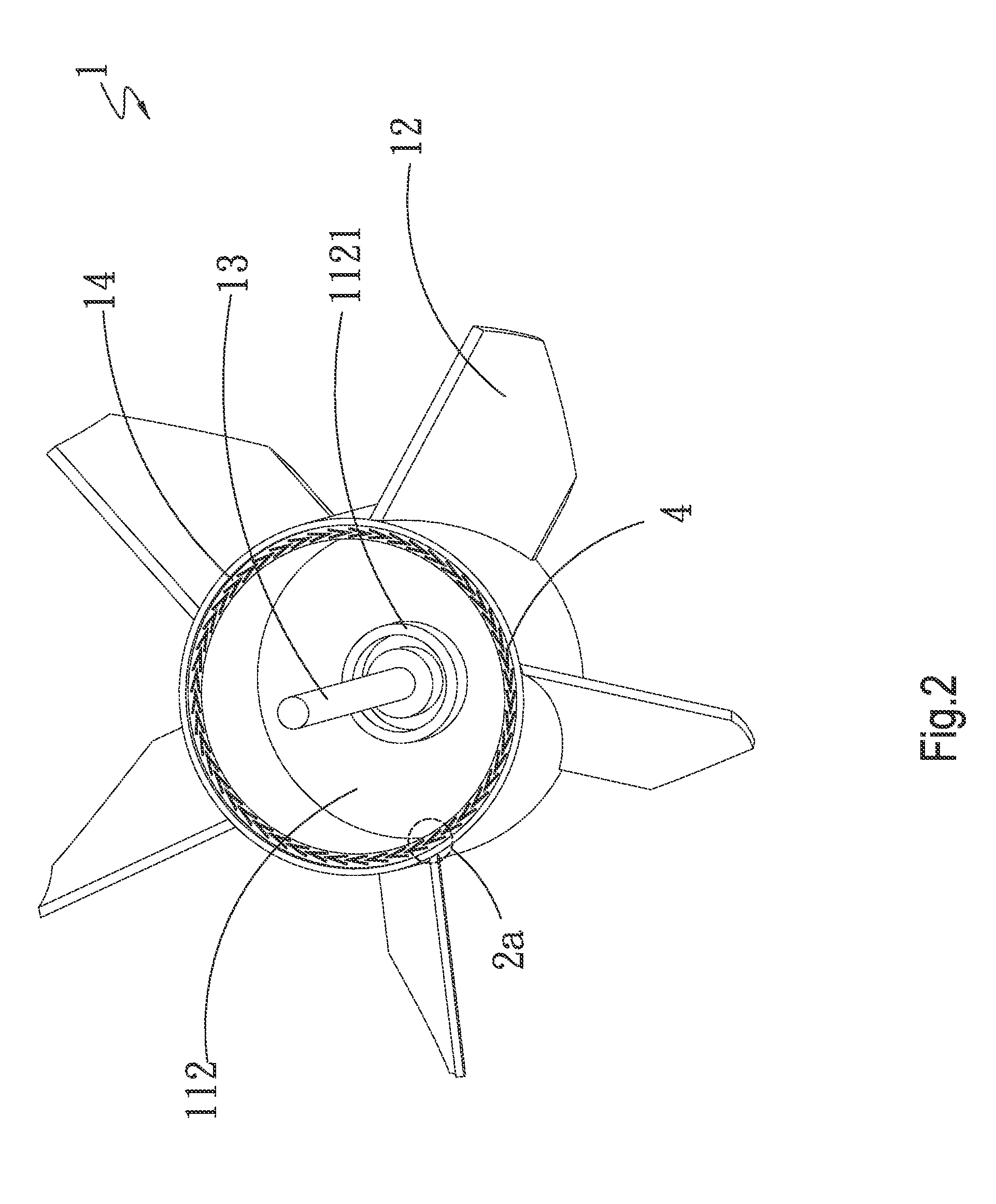
[0024]The rotor 1 includes a main body 11 and a plurality of blades 12. The main body 11 has an open rear end 111 and a closed front end 112. The closed front end 112 is provided on an inner face with a centered shaft mounting portion 1121, and a shaft 13 of the rotor 1 has a proximal end inserted in the shaft mounting portion 1121. The blades 12 are spaced along an outer circumferential surface of the main body 11 to radially outward extend from the main body 11. A magnetic body 14 is annularly mounted on an inner circumferential surface of the main body 11, and has a rear free end face 141.
[0025]The frame 2 includes a sleeve 21 and at least one bearing 22 rotatably received in the sleeve 21. The bearing 22 has an axial bore 221, into which a distal end of the shaft 13 is in...
second embodiment
[0028]The first pressurizing sections 4 are provided on the magnetic body 14 to space along the rear free end face 141 thereof. Alternatively, according to the present invention as shown in FIG. 3, the first pressurizing sections 4 are provided on the front face 321 of the base plate 32 of the stator assembly 3 to space along a peripheral edge of the base plate 32.
[0029]The first pressurizing sections 4 according to the present invention can be provided in two different manners. Please refer to FIG. 2a that is an enlarged view of the circled area 2a of FIG. 2 showing a first manner of providing the first pressurizing sections 4. In this first manner, the first pressurizing sections 4 are sunk into the rear free end face 141 of the magnetic body 14. FIG. 4 is another rear perspective view of the rotor 1 and FIG. 4a is an enlarged view of the circled area 4a of the FIG. 4. In FIGS. 4 and 4a, there is shown a second manner of providing the first pressurizing sections 4. In the second m...
PUM
 Abstract
Description
Claims
Application Information