Method of Increasing the Performance of a Carbonaceous Fuel Combusting Boiler System

a carbonaceous fuel and boiler system technology, applied in the direction of steam engine plants, machines/engines, steam regeneration, etc., can solve the problems of significant increase of lpeco, reduced efficiency, low heat transfer coefficient, etc., and achieve the effect of increasing the power of a carbonaceous fuel combusting boiler, without substantially decreasing the thermal efficiency

Inactive Publication Date: 2011-04-28
FOSTER WHEELER ENERGY CORP
View PDF4 Cites 30 Cited by
  • Summary
  • Abstract
  • Description
  • Claims
  • Application Information

AI Technical Summary

Benefits of technology

[0009]An object of the present invention is to provide a method of increasing the power of a ...

Problems solved by technology

A difficulty with an LPECO is that to avoid condensation of acid compounds in the flue gas on the heat exchange surfaces of the LPECO, the feedwater, heated by steam extracted from the turbines, has to be initially at a certain temperature, for example, above 120° C. for high sulfur fuel.
Such a high water inlet temperature to the LPECO leads to a low heat ...

Method used


Image

  • Method of Increasing the Performance of a Carbonaceous Fuel Combusting Boiler System
  • Method of Increasing the Performance of a Carbonaceous Fuel Combusting Boiler System

Examples


example 1

Air-Fired Sub-Critical PC Boiler

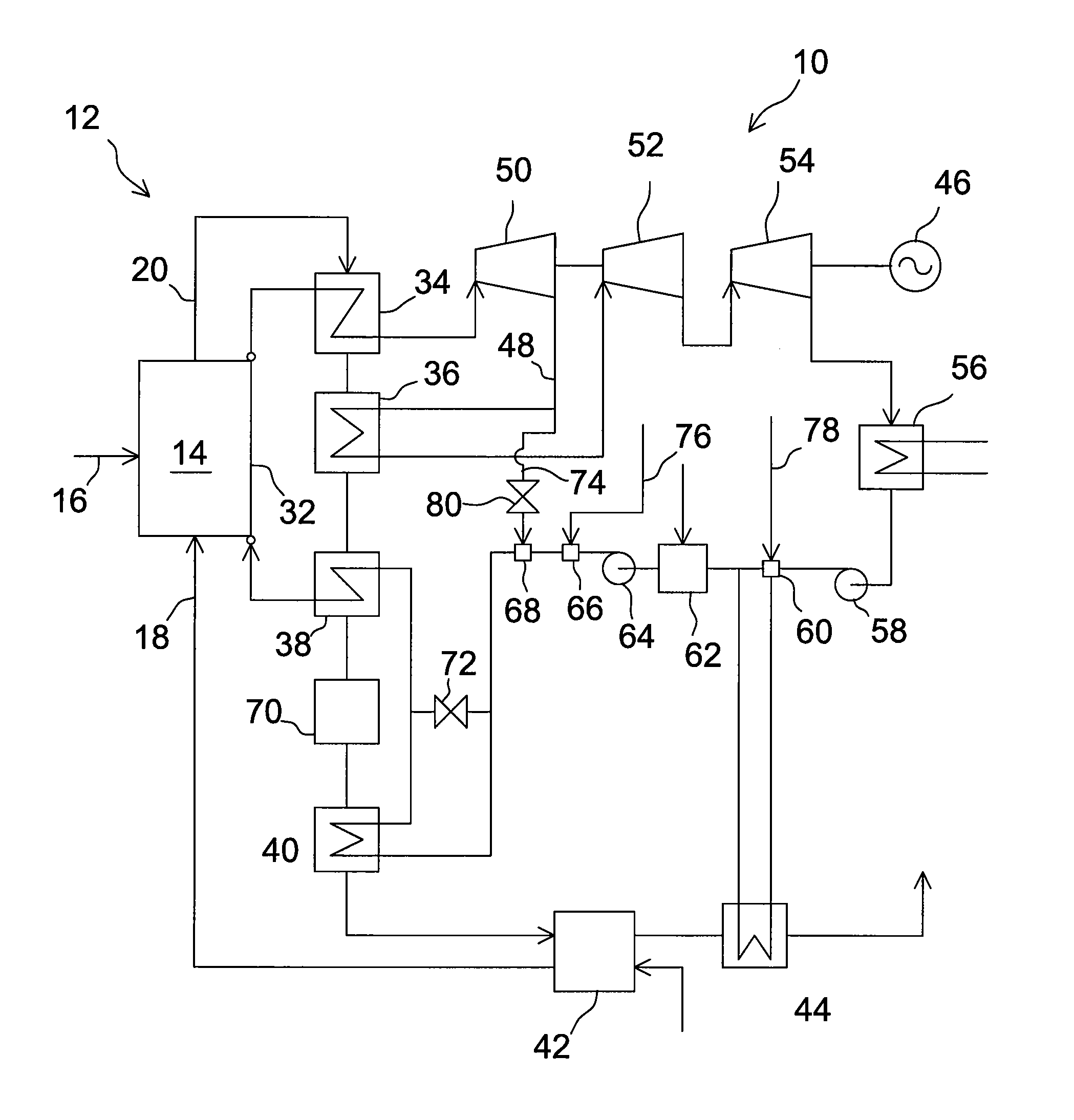
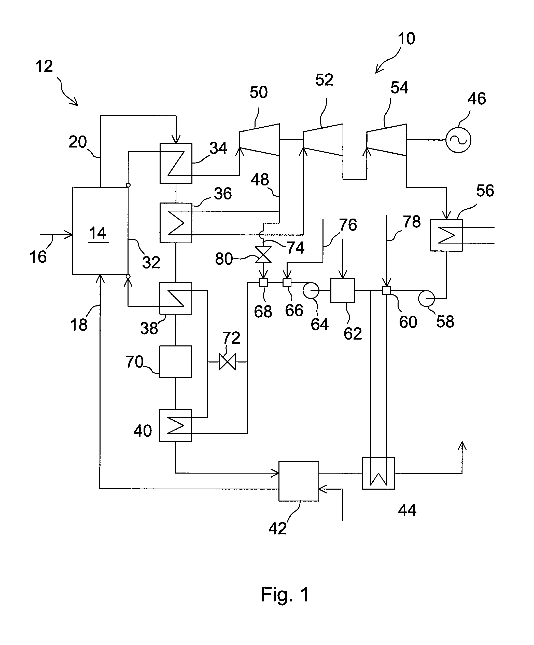
[0032]Below are described the main results of a calculation of the effects of the present invention in a sub-critical PC boiler with reheat, fired with lignite fuel. The arrangement of heat exchangers arranged in series in the HRA includes RH, SH, ECO, GH and LEPCO. In this example, the reference case includes steam extraction from an HPST section, which will be shut off in the new case. In the example, the low temperature feedwater is heated up by an enlarged economizer to the same temperature as in the reference case, which results in no change of evaporation duty in the furnace. The heat transfer to the combustion air at the GH is reduced due to a lowered temperature of the flue gas entering the GH. As a result, the boiler fires more fuel to compensate for the low inlet air temperature. Thus, the increased firing of fuel does not increase the total heat flux in the furnace. Due to the increased reheat steam flow, the reheat duty is increased. It is...

example 2

Air-Fired Super-Critical PC Boiler

[0035]Below are described the main results of a calculation of the effects of the present invention in an SC PC boiler, with an RH and a parallel pass HRA. Two cases, named New 1 and New 2, are analyzed, corresponding to the shutting off of one, and one and one-half, correspondingly, of two high-pressure steam extractions from the high pressure steam turbine section.

[0036]Due to shutting off of the high pressure steam extractions, the temperature of the feedwater decreases from 298° C. by 32° C. and 52° C. for the cases of New 1 and New 2, the duty of the economizer rises by 60% and 120%, respectively, but the evaporation and superheat is kept unchanged. The RH steam flow and duty increase by 7% and 14%, respectively. The gas temperature to the economizer rises due to increased firing and flue gas flow, but the temperature of the flue gas at the inlet of the GH drops due to increased economizer duty, which leads to a lowering of the air temperature ...


PUM


Abstract

A method of increasing the power of a carbonaceous fuel combusting boiler system includes the steps of (a) feeding carbonaceous fuel into a furnace of the boiler system, (b) feeding oxidant gas into the furnace for combusting fuel to produce exhaust gas, (c) discharging the exhaust gas from the furnace via an exhaust gas channel, (d) conveying a stream of feedwater from a boiler economizer arranged in the exhaust gas channel to evaporating and superheating heat exchange surfaces arranged in the furnace and in the exhaust gas channel for converting the feedwater to superheated steam, (e) expanding the superheated steam in a high-pressure steam turbine for generating power, (f) extracting steam from the high-pressure steam turbine at a decreased rate for preheating the feedwater, (g) conveying steam from the high-pressure steam turbine at an increased rate to a reheater arranged in the exhaust gas channel for generating reheated steam, (h) expanding the reheated steam in an intermediate pressure steam turbine for generating power, and (i) conveying the exhaust gas in the exhaust gas channel from the reheater through a boiler economizer to a gas heater. The heat exchange surface area of at least one of the reheater and the boiler economizer is increased and/or a high pressure economizer is added downstream of the boiler economizer and upstream of the gas heater.

Description

BACKGROUND OF THE INVENTION[0001]1. Field of the Invention[0002]The present invention relates to a method of increasing the performance, i.e., the thermal efficiency and / or power of a carbonaceous fuel combusting boiler system.[0003]2. Description of the Related Art[0004]In a carbonaceous fuel combusting boiler system, the flue gas discharged from a furnace along a flue gas channel is cooled down in a heat recovery area (HRA), including superheater (SH) and reheater (RH) sections, downstream of which the heat is recovered by a boiler economizer (ECO) to heat up feedwater, followed by a gas heater (GH), such as an air heater, to heat up oxidant gas for the combustion. The superheated steam is expanded in a high-pressure steam turbine (HPST). At least a portion of the expanded steam is reheated in the RH section and conducted to an intermediate-pressure steam turbine (IPST), and further, to a low-pressure steam turbine (LPST). The expanded steam is cycled back to the boiler via a cond...

Claims


Application Information

Patent Timeline
IPC IPC(8): F01K7/22F01K13/02F01K11/02F01K19/00
CPCF01K7/22F01K13/02F01K7/40F01K7/38
Inventor FAN, ZHENHACK, HORSTSELTZER, ANDREW
Owner FOSTER WHEELER ENERGY CORP
Why Eureka
Try Eureka