
Operating parameter monitoring circuit and method

Active Publication Date: 2011-05-05
ARM LTD
View PDF10 Cites 16 Cited by
  • Summary
  • Abstract
  • Description
  • Claims
  • Application Information

AI Technical Summary

Benefits of technology

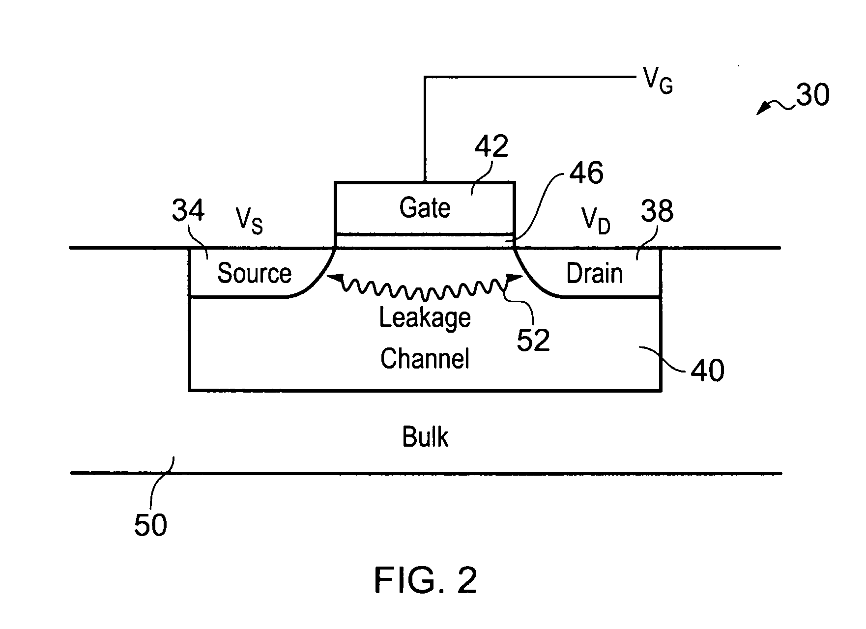
[0011]The ring oscillator has at least one inverting stage comprising at least one leakage transistor operable in a leakage mode and a capacitive element arranged to be charged or discharged in dependence on a leakage current through the at least one leakage transistor. The leakage current through the at least one leakage transistor has a predictable variation with a number of operating parameters which can be monitored with the monitoring circuit. As the leakage current varies with the operating parameter, the rate at which the capacitive element is charged or discharged varies accordingly. This means that the rate at which the oscillating signal propagates through the ring oscillator circuit is dependent on the operating parameter and hence the oscillation period is an indicator of the operating parameter. Operating the ring oscillator in this way provides a small, low cost, and low power monitoring circuit whilst providing the ability to monitor a variety of parameters of the integrated circuit.
[0044]The second capacitive element may comprise at least one inverter. The inverter has a certain amount of capacitance associated with it. The more inverters that are used to form the second capacitive element, the greater the capacitance of the second capacitive element and hence the greater the time taken to charge the second capacitive element as a whole.

Problems solved by technology

A problem with such mechanisms is that the relationship between oscillation frequency and temperature can be complex and the ring oscillator may require relatively complicated biasing circuits and / or analogue outputs.
As process geometries diminish in size, local variation of basic MOSFET characteristics become so large that simple chip-level guard-banded designs become heavily over designed and inefficient.
Accordingly, relying on a simple set of boundary-provided wafer acceptance test MOSFET parameters will be less accurate than system-on-chip embedded MOSFET monitors due to context-dependent effects and local variations that cannot be monitored from the distant areas where wafer monitors are provided.

Method used


Image

  • Operating parameter monitoring circuit and method
  • Operating parameter monitoring circuit and method
  • Operating parameter monitoring circuit and method

Examples


Embodiment Construction

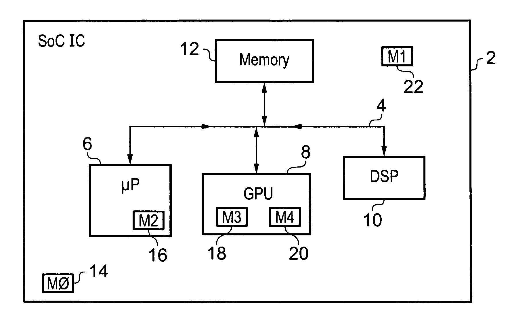
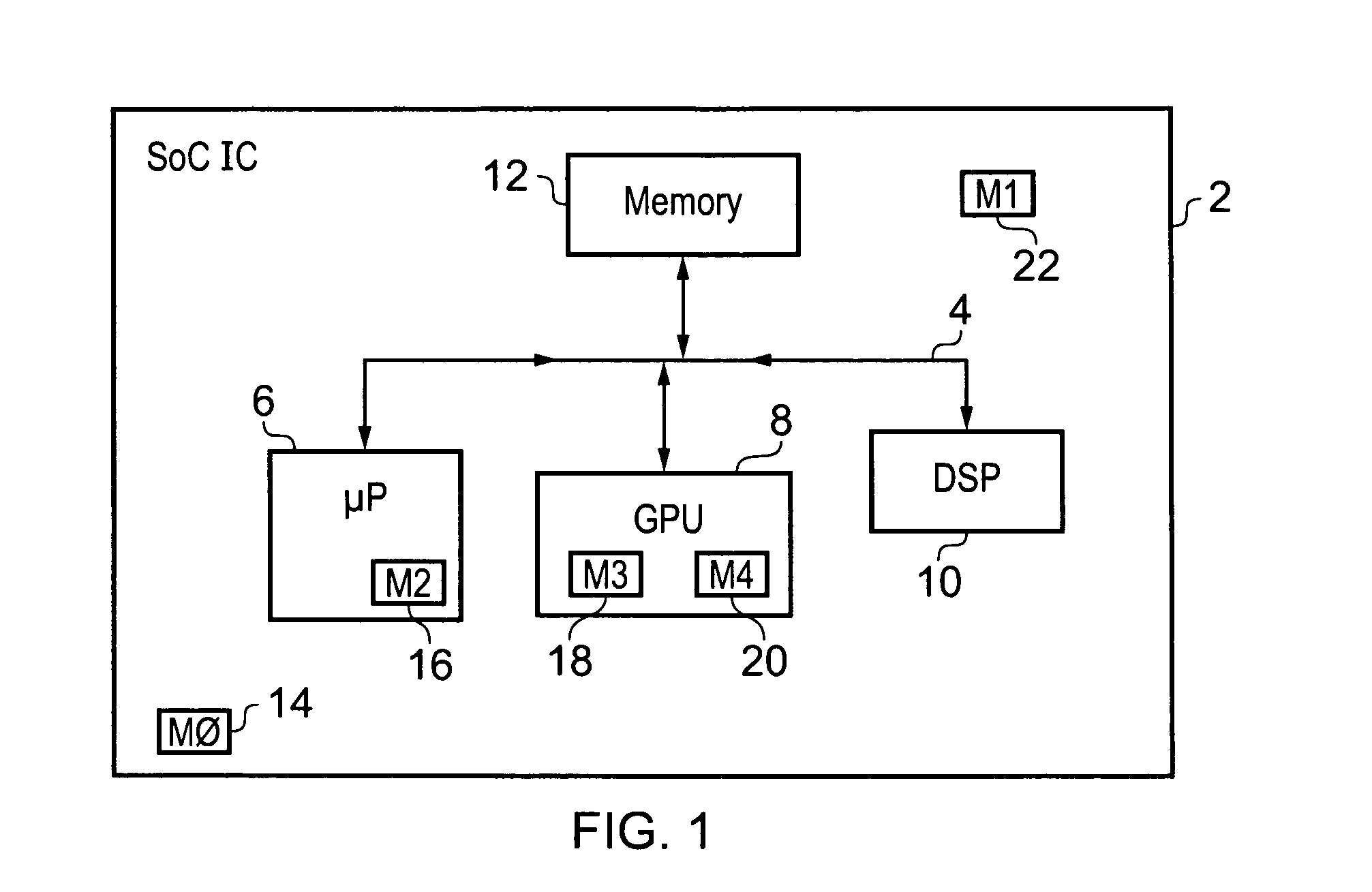
[0101]FIG. 1 schematically illustrates a system-on-chip integrated circuit 2 including a plurality of functional units 6, 8, 10, 12 interconnected via a system bus 4. The functional units include a processor core 6, a graphics processing unit 8, a digital signal processor 10 and a memory 12. It will be appreciated that the present techniques are applicable in a wide variety of different integrated circuits and that the precise arrangement of functional units is not important.

[0102]Located within the integrated circuit 2 are a plurality of monitoring circuits 14, 16, 18, 20, 22. The monitoring circuit 16 is located within the processor 6 and serves to monitor an operating parameter of the processor 6. This operating parameter may be, for example, threshold voltage levels associated with a low power state for reducing leakage current, an operating voltage, an operating temperature or the like. In a similar way, there are monitoring circuits 18, 20 embedded within the graphics processi...


PUM


Abstract

A monitoring circuit 14, 16, 18, 20, 22 for monitoring an operating parameter of an integrated circuit 2 comprises a ring oscillator circuit 80 comprising a plurality of serially connected inverting stages 82-1, 82-2, 82-3.At least one of the inverting stages 82-1, 82-2 comprises at least one leakage transistor 64-1, 64-2 which is configured to operate in a leakage mode in which substantially all current through the at least one leakage transistor is a leakage current, and a capacitive element 70-1 arranged to be charged or discharged in dependence on the leakage current. The ring oscillator circuit 80 thus generates an oscillating signal with an oscillation period dependent on a rate at which the capacitive element 70-1 is charged or discharged. The operating parameter controls a magnitude of the leakage current so that the oscillation period indicates the operating parameter.

Description

FIELD OF THE INVENTION[0001]The present invention relates to the field of integrated circuits. More particularly, this invention relates to monitoring an operating parameter within an integrated circuit.DESCRIPTION OF THE PRIOR ART[0002]It is known to provide an integrated circuit with one or more monitoring circuits which seek to provide monitoring information regarding operating parameters of the integrated circuit. A typical operating parameter to be monitored is operating temperature. Other operating parameters which may be monitored include an operating voltage. This information can be used to ensure correct operation of the integrated circuit and may, in some circumstances, be used to adjust the operation using a feedback mechanism.[0003]It is known to provide ring oscillator circuits in which the oscillation frequency gives an indication of the operating temperature of an integrated circuit. As the integrated circuit heats up, the transistors making up the inverter chain with...

Claims


Application Information

Patent Timeline
IPC IPC(8): G01R27/26
CPCH03K3/0315G01R31/2621
Inventor MYERS, JAMES EDWARDFLYNN, DAVID WALTERIDGUNJI, SACHIN SATISHYERIC, GREGORY MUNSON
Owner ARM LTD
Learn More