Delayed optical logic gates

a technology of optical logic and delay, applied in the field of delay optical logic gates, can solve the problems of data traffic in fiber-optic communication lines that needs to be temporally delayed, and the all-optical active buffer memory has not been implemented

Active Publication Date: 2011-05-19
GWANGJU INST OF SCI & TECH +1
View PDF4 Cites 4 Cited by
  • Summary
  • Abstract
  • Description
  • Claims
  • Application Information

AI Technical Summary

Benefits of technology

[0014]The delayed optical logic gates have functions of dynamically controllable delay-time of the incoming signal light using slow light phenomenon, where the delay-time of the logic gates is controllable by adjusting another coupling light intensity to affect on the group delay of the slow light. The switching time for each signal light pulse limits in phase decay time of the optical nonlinear medium (B. S. Ham, Applied Physics Letters, Vol. 85 (No. 6), pp. 893-895 (2004); Physical Review B, Vol. 68 (No. 7), pp. 023811 (2003); U.S. Pat. No. 6,628,453). However, the bandwidth of the delayed optical logic gates or overall gating speed is invariant of the group delay of the slow light because the bandwidth of ‘IN’ and ‘OUT’ across the nonlinear medium used for the delayed optical logic gates is same. Main advantage of the present invention of the delayed optical logic gates is the data delay-time controllability useful for a slow electronic device to alleviate processing power toward high-speed optical data rates.
[0015]Briefly described, a system of the delayed optical logic gates of the present invention is provided by multiply connected delayed optical routers composed of a nonlinear optical medium and coherent light pulses. The nonlinear optical medium of the delayed optical logic gates is composed of at least three-energy levels. Two of them should be closely spaced on the ground states, and the third one should be an excited state. The frequencies of the laser light of C and A are either same or different depending on purposes: See FIG. 1. The light pulse A is used as a control for nondegenerate four-wave mixing processes to generate the output pulse D. The nondegenerate four-wave mixing output D can be used as an input(s) to the second nonlinear medium to configure the present invention of the delayed optical logic gates. In FIG. 1 the output S is the slow light of the input light P. According to nondegenerate four-wave mixing process, S and D are alternative. Each light pulse can be guided by an optical waveguide, free space, or surface plasmon optical waveguide. The optical waveguide is not part of the current invention. By connecting two or more delayed optical routers, the present invention of the delayed optical logic gates performs the Boolean logic: NOT, NAND, AND, OR, XOR, and NOR. The delayed optical logic gates can be applied for scalability purposes. The transmission time between two delayed optical logic gates is negligible because the light pulse moves almost speed of light.
[0016]To achieve these and other advantages as described above and in accordance with the purpose of the present invention, this specification provides a method for operating a logical gate using at least one delayed optical router comprising a nonlinear optical medium, wherein the nonlinear optical medium comprises two closely spaced ground states such that a transition between said two ground states is dipole forbidden, and an excited state such that two-photon transitions between said two ground states via said excited state are allowed, the method comprising:
[0017]using at least one of a slow light (S) and a nondegenerate four-wave mixing signal (D) as a result of Boolean algebra,
[0018]wherein the slow light (S) is appeared by applying, to the nonlinear optical medium, a first laser beam (P) with a first frequency corresponding to a first transition between a first ground state of the two ground states and the excited state and a second laser beam (C) with a second frequency corresponding to a second transition between a second ground state of the two ground states and the excited state; and the nondegenerate four-wave mixing signal (D) is appeared by applying, to the nonlinear optical medium, the first laser beam (P) with the first frequency, the second laser beam (C) with the second frequency and a third laser beam (A) with a third frequency corresponding to the second transition.
[0019]This specification also provides a method of operating a logical gate using at least one delayed optical router comprising a nonlinear optical medium, wherein the nonlinear optical medium comprises two closely spaced ground states such that a transition between said two ground states is dipole forbidden, and an excited state such that two-photon transitions between said two ground states via said excited state are allowed, the method comprising: a) applying, to said nonlinear optical medium, a first laser beam (P) at a first frequency corresponding to a first transition between a first ground state of said two ground states and said excited state; b) applying, to said nonlinear optical medium, a second laser beam (C) at a second frequency corresponding to a second transition between a second ground state of said ground states and said excited state; c) applying, to said nonlinear optical medium, a third laser beam (A) at a third frequency corresponding to the second transition between the second ground state of said ground states and said excited state; d) adjusting an intensity of said second laser beam (C) to produce a slow light (S), wherein said slow light (S) corresponds to a group velocity slow down of said first laser beam (P); e) adjusting at least one of intensities of said first laser beam (P), said second laser beam (C), said third laser beam (A), to produce a nondegenerate four-wave mixing signal (D) at a frequency corresponding to a two-photon coherence excitation [ReρI2]2, wherein said slow light (S) is disappeared in response to the producing of said nondegenerate four-wave mixing signal (D); and f) using at least one of said produced slow light (S) and said nondegenerate four-wave mixing signal (D) as a result of a logical gate.

Problems solved by technology

However the electronics is much slower than optics.
Unfortunately all-optical active buffer memory has not been implemented, yet.
Thus, more often it is required that the data traffic in fiber-optic communication lines need to be temporally delayed for some data processing purposes.

Method used


Image

  • Delayed optical logic gates
  • Delayed optical logic gates
  • Delayed optical logic gates

Examples


Embodiment Construction

[0035]To get a better understanding, reference is now made to the drawings which illustrate the preferred embodiments of the present invention.

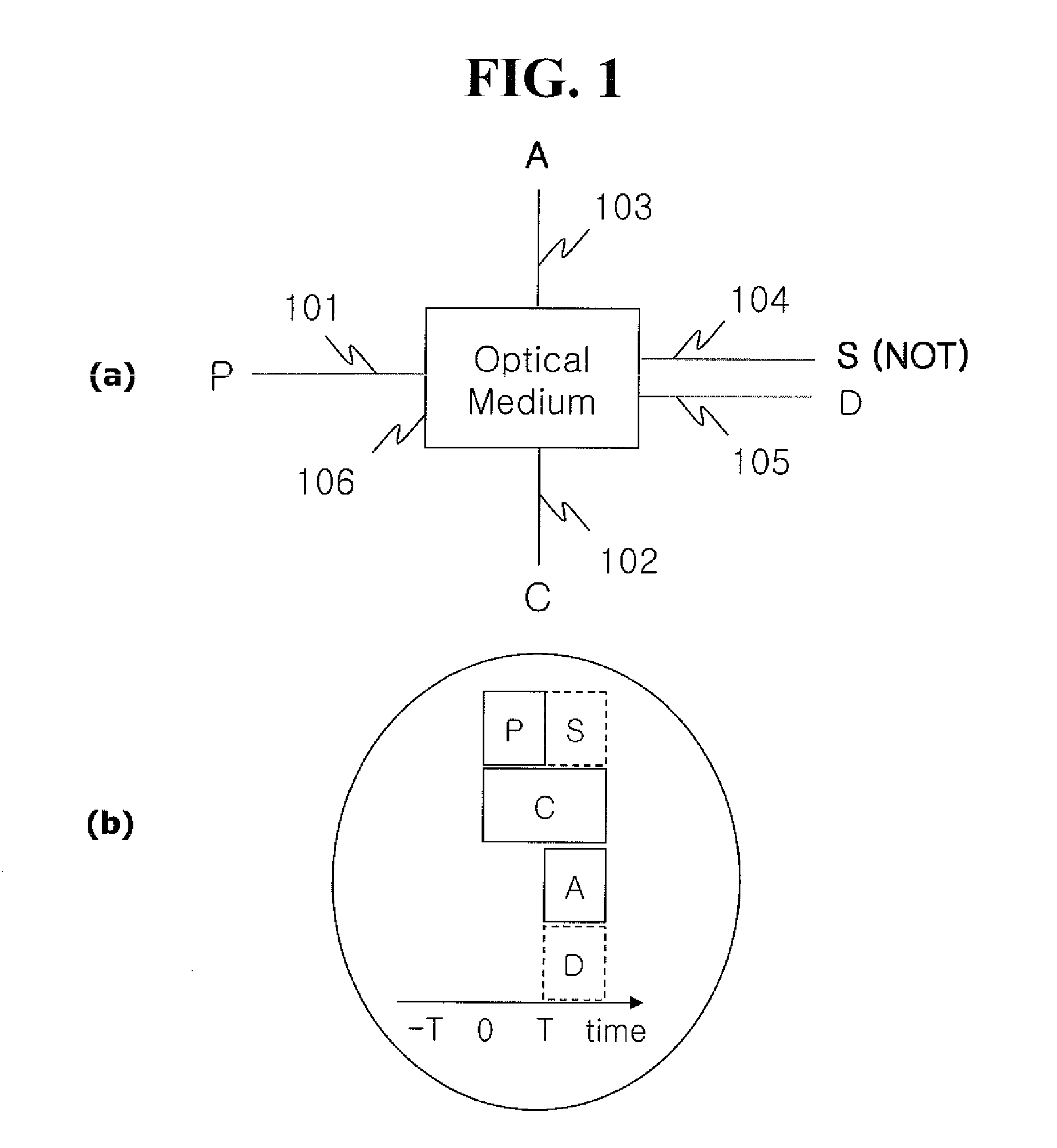
[0036]FIG. 1 (a) shows a delayed optical router as a basic building block for the present invention of the delayed optical logic gates.

[0037]FIG. 1(a) describes a delayed optical logic gate, NOT, where a single delayed optical router is used. Letters P, C, A, S, and D stand for light pulse at different propagation directions kP, kC, kA, kS, and kD, respectively. The numbers from 101 to 105 stand for lights as well as physical channels such as optical waveguide or free space used for the laser beams. The number 106 stands for a nonlinear optical medium. According to the delayed optical router, which will be explained below, the output S (104) is always OFF whenever the logical input light A (103) is switched ON, and vice versa. Here it should be noted that the light C may be continuous if the frequency of the light C is different from the ligh...


PUM

PropertyMeasurementUnit
frequencyaaaaaaaaaa
conduction bandaaaaaaaaaa
sizeaaaaaaaaaa

Abstract

A system, method, and apparatus for delayed optical logic gates based on slow light and enhanced nondegenerate four-wave mixing processes, where a single or multiple delayed optical routers are utilized for dark resonance interactions in which two-color lasers interact with a three-level nonlinear optical medium comprised of two ground states and one excited state through the nondegenerate four-wave mixing processes. The delayed optical logic mechanism is based on combination of single or multiple dark resonance-induced two-photon coherence conversion via slow light phenomenon. The two-photon coherence induced on the ground states is optically detected via nondegenerate four-wave mixing processes. The nondegenerate four-wave mixing generation is enhanced owing to dark resonance or electromagnetically induced transparency. The gating time and bandwidth of the present delayed optical logic gates is invariant to the delayed time of the delayed optical router because IN and OUT bandwidth across the nonlinear medium must be same. The present invention of delayed optical logic gates have potential to keep up ultra-high-bandwidth optical information processing using relatively slow electronic processing devices.

Description

CLAIM OF PRIORITY[0001]This application is a divisional application of U.S. patent application Ser. No. 12 / 280,923, “DELAYED OPTICAL LOGIC GATES,” filed on Aug. 27, 2008, by Ham, Attorney Docket No. PARK-01001US0, which claims priority to Korean Patent Application No. 10-2007-0126380 filed on Dec. 6, 2007, Korean Patent Application No. 10-2007-0126381, filed on Dec. 6, 2007, and PCT Patent Application No. PCT / KR2007 / 006846 filed on Dec. 26, 2007, all of which are incorporated herein by reference.BACKGROUND OF THE INVENTION[0002]1. Field of the Invention[0003]The present invention relates to a method and apparatus for delayed optical logic gates, where the physics lies in quantum-coherence-based slow light and enhanced nondegenerate four-wave mixing processes.[0004]2. Description of the Related Art[0005]In an electronic transistor, the switching time is determined by the carriers' transfer time across a gate, where the size of the transistor gate has been decreased for last three dec...

Claims


Application Information

Patent Timeline
Patent Type & Authority Applications(United States)
IPC IPC(8): G02F3/00H04B10/29
CPCG02F3/00G02F1/3536H04Q11/0005H04Q2011/002
Inventor HAM, BYOUNG-SEUNG
Owner GWANGJU INST OF SCI & TECH
Why Eureka
Try Eureka