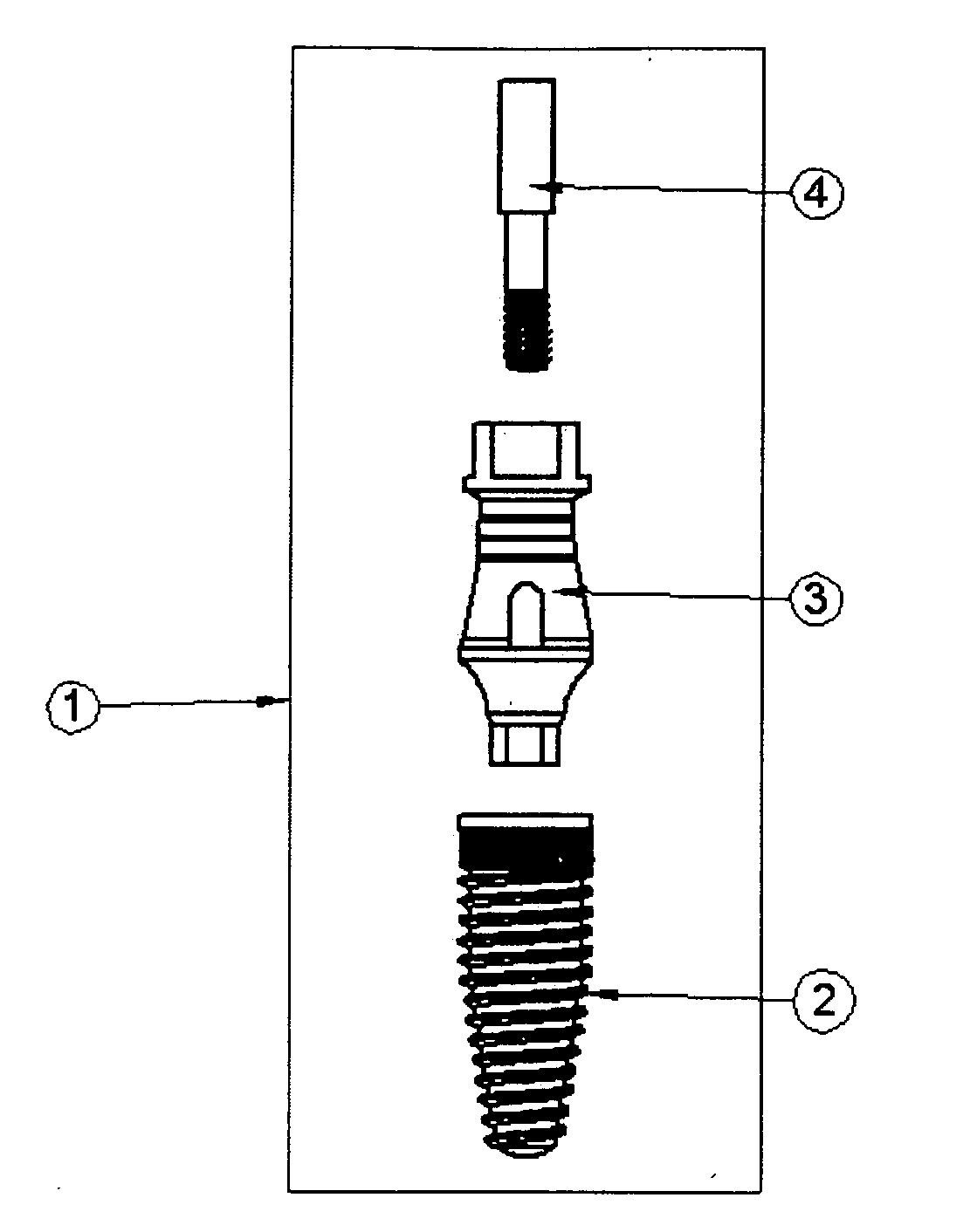
Dental implant system
Active Publication Date: 2011-05-19
COUNCIL OF SCI & IND RES
19 Cites 60 Cited by
AI-Extracted Technical Summary
Problems solved by technology
Both the inadequate forces (no stimulating factor due to stress shielding effect) and excessive forces (shearing forces) lead to bone resorption.
However none have showed ...
Method used
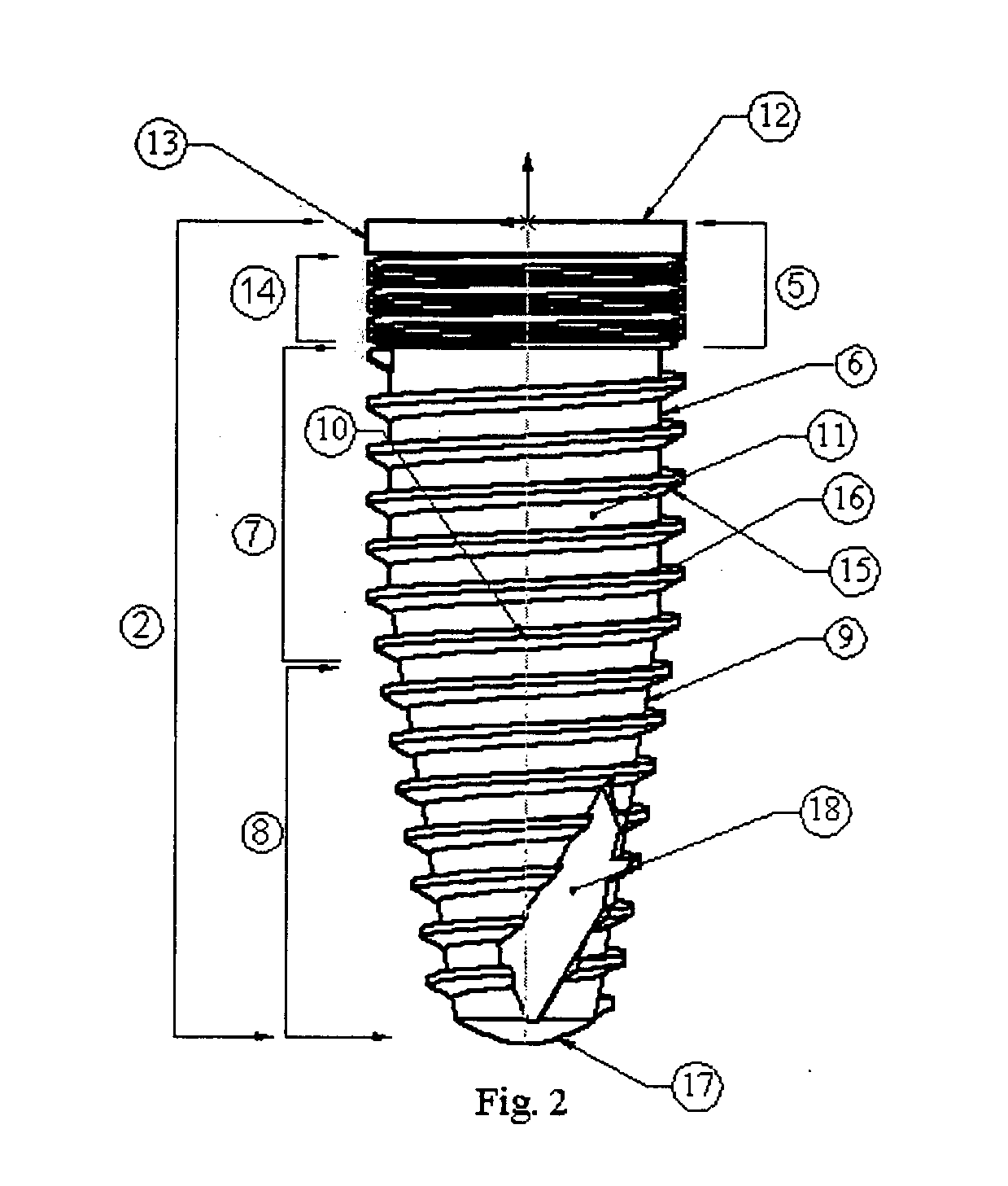
[0130]The implant fixture has a long axis (10) parallel to the three parts of the implant. The body of the implant (11) consists of the second part and third part of the implant fixture (2), has conical and cylindrical shape, which helps in easy insertion during implant fixture (2) placement and in acquiring the primary stability for better osseointegration respectively. The tapering structure also helps the implant fixture (2) in avoiding impingement on the anatomical structures.
[0132]The first part/crestal module (5) of the implant has flat platform (12) on the top and consist of two portions, the surface treated non-threaded collar (13) and the roughened micro threaded area (14). The surface treated non-threaded collar (13) has paralleling sides (6) with rough surface and has length of 0.4-0.8 mm. This enhances better soft tissue and bone integration around the implant fixture (2). The micro threaded area (14) covers about 1.2-1.6 mm of the implant fixture (2) surface. This enhances the surface area of the crestal module (5) which favorably distributes the forces at the critical area of alveolar bone crest.
[0135]There is a particular type of threads (15) in the intermediate (7) and apical portion (8) (implant body 11) of the implant fixture (2) thus covering more than ⅔ portion of the implant (2). This enhances the surface area of the implant fixture (2) and thus its osseointegration with the bone.
[0136]One of the preferred embodiments of the implant fixture (2) with tapering apical part (8) having rounded apical end (17) which prevents damage to vital structures even if the implant is placed in close vicinity or pressing against it. The embodiment also shows a vertical apical recess (18) which allows the collection of the bone chips as the implant is self-tapping and the borehole preparation is lesser than the diameter of the implant fixture (2).
[0138]The threads (15) have a buttress shape, with flat top surface and tapering lower surface. The top surface (21) makes 90° angulation with the long axis (10) of the implant fixture (2). The lower surface anglulation (obtuse) (22) with the long axis (10) of the implant fixture (2) falls in the range of about 110°-135° degrees. Threads (15) have a depth (23) in the range of about 0.275-0.375 mm, pitch (24) in the range of 0.5-0.85 mm, and pitch surface (25) in the range of 100-150 um. Buttress threads (15) are incorporated in the implant fixture (2) to have self-tapping nature for easy insertion into the bone and better primary stability, while producing moderate amount of forces at the crest under different type of forces with comparable shearing component of the axial load at implant bone interface.
[0139]As in FIG. 2 and FIG. 3 the implant fixture (2) embodiment shows a unique combination of the buttress threads (15) on the implant body (11) i.e. more than ⅔rd part of the implant fixture (2) and micro threads (14) on the crestal module (5) of the implant fixture (2). This unique combination of the implant design has reduced stresses at the implant abutment interface and at the critical crestal level of alveolar bone and also it makes the implant fixture (2) of self-tapping nature. These findings have been substantiated by our FEA study done to compare the different types of threads (Buttress, V shape, reverse Buttress and Buttress with micro threads) under three types (compression, tension and moment) of forces.
[0140]FIG. 4 shows one of the preferred longitudinal cross-sectional implant fixture (2) embodiments having the internal connection (26) for connecting the implant fixture (2) with the abutment (3). The internal connection (26) extends from the crestal module portion (5) of the implant fixture (2) upto the middle portion (7). The internal connection (26) has three sections, the leading internal bevel (27), internal hex chamber (28) and threaded channel (29). The leading internal bevel has an angulation with the long axis (10) of the implant fixture (2) in the range of 10-20 degrees for easy insertion of the abutment (3) into the implant fixture (2) and to have a better emergence profile for enhancing the overall esthetics of the prosthesis. The internal hex chamber (28) has a hexagonal shape with the height in the range of 1-2 mm. The threaded channel (29) allows proper seating and retention of the abutment screw and about 2-3 mm.
[0147]FIG. 7 shows the longitudinal section of the internal portion (48) of the multifunctional component (3). The internal portion (48) is similarly divided into upper (49), middle (50) and lower portion (51) as the external surface of the multifunctional component (3). The upper portion (49) from the top consist of square shape wide opening (52) which helps in easy access for engagement of the abutment screw (4) and implant driver. The upper portion consists of hexagonal shape recess (53) for securing the implant driver. The middle portion (50) consists of internal channel (54) with circular shape for passing the abutment screw (4). The lower portion (51) also has internal channel (54) for passing the abutment screw (4) however, there is an additional threaded portion (55) which helps in securing the screw (4) and avoids its sudden fall from the multifunctional component after the screw (4) get disengaged from the implant (4) internal channel (29). In one of the preferred embodiments, the internal portion (48) of the multifunctional component (3) has a decreasing diameter of 3.5 mm to 1.85 mm from the upper portion (49) to lower portion (51).
[0152]The upper portion of the external surface of implant is the region surrounded by the crest of bone. The mechanical stresses falling at the crest play a critical role in its resorption. Both the inadequate forces (no stimulating factor due to stress shielding effect) and excessive forces (shearing forces) lead to bone resorption. There are different types of crestal module of the implant depending upon the shape (cylindrical, tapered, reverse tapered), size (long, medium, short), and surface texture (smooth, polished, rough). However none have showed the ability of modulating the stresses at the crestal region, which can decrease the resorption of the bone. In the present invention microthreads are incorporated at the crestal m...
Benefits of technology
[0031]The primary objective of the present invention is to provide the surgical dental implant system capable of being machined and fabricated conveniently and economically, made up of any b...
Abstract
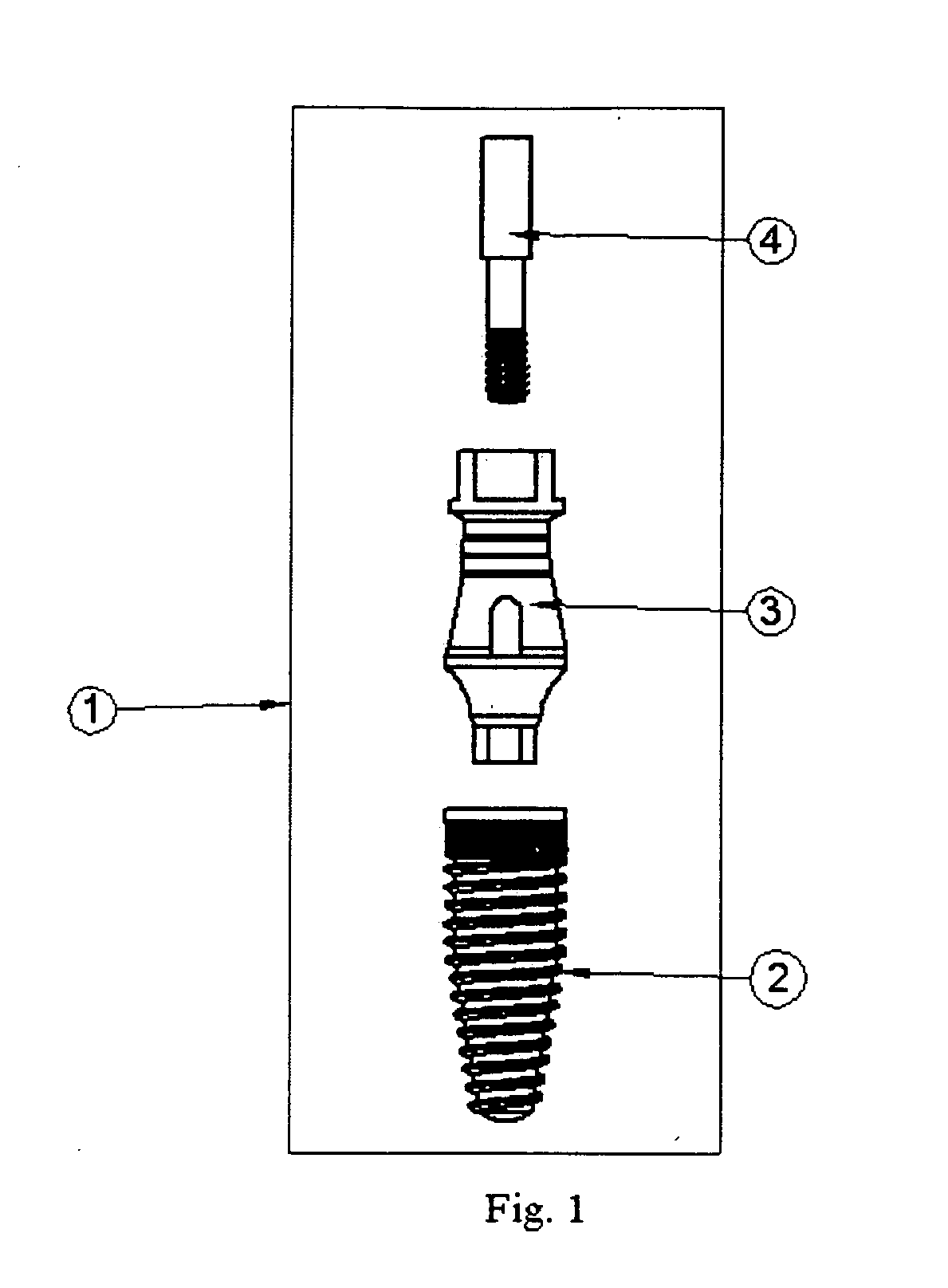
The invention provides a screw type dental implant system (1), comprising three components namely-Dental implant fixture (2), Multifunctional component (3) and the Abutment screw (4). The invention includes screw shape dental implant fixture with external surface having Buttress threads on the body and micro threads at the collar of particular dimensions. This combination provides advantages of improved biomechanics at the implant abutment interface, self-tapping nature to the implant and minimizes the stresses at the crest of the bone leading to decrease resorption of crestal bone during the implant functioning thus ensuring long-term implant stability. The multifunctional component of the system serves the purpose of implant mount, impression analog and final abutment. In addition the multifunctional component has a single prosthetic platform so one component is compatible with different implant dimensions. Thus the multifunctional component minimizes the inventory needed for the implant system and allows easy handling of the system. The implant abutment connection has internal type interface with medialized implant abutment junction allowing better maintenance of crestal bone level. The abutment has an external concave transmucosal portion for enhancing the emergence profile and additional internal threads for securing the loosened abutment screw. The abutment screw has long internal channel, which can be adjusted according the height of abutment without loosing its fastening property.
Application Domain
Dental implants
Technology Topic
ProsthesisAbutment Screw +8
Image
Examples
- Experimental program(9)
Example
Example 1
Finite Element Study in Support of the Present Invention
[0165]Finite Element Analysis (FEA) is a computer based numerical technique for solving wide range of engineering problems. It can be used to calculate deflection, stress, strain, vibration response, buckling behavior and many other phenomena. It can also used to analyze wide range of material models such as isotropic, orthotropic, anisotropic etc., FEA is be used to simulate the wide range of material response such as linear/non-linear response, elastic and plastic deformation and also time independent/dependent material responses. The computer is required because of the considerable number of numerical calculations required to analyze the structure behavior for the given external loads. A mesh is needed in FEA to divide the whole domain into elements.
Discretization of a Domain
[0166]It is the process of creating a mesh, elements and their respective notes and defining boundary conditions. In the Finite Element method, a structure is discretized into many small simple blocks or elements. The behavior of the each element can be described using a relatively simple set of equations. Just as a set of elements can be joined together to build a whole structure, likewise the equations describing the behavior of individual elements are joined into an extremely large set of equations that describe the behavior of the whole structure. From the solution, the computer extracts the behavior of individual elements. From this it can calculate the stress and deflection of all the parts of the structure.
Derivation of Element Equations
[0167]Finite Element (FE) model generated as a solid model with the solid element mesh of individual elements and perform the pre-process, solution and post processing to calculate the stresses and strains.
[0168]The study of solid mechanics is concerned with the equations of the equilibrium, strain-displacements relations and the constitutive law. It is well known that the assumption of the strains being infinitesimal leads to a linear analysis, while the use of generalized Hooke's law between stress and strain give rise to a linear elastic-plastic analysis, viscoelastic or viscoplastic models can be incorporated by using appropriate constitutive modeling. Retaining the higher order terms in strain displacement relations can simulate geometric nonlinear effects in solid mechanics.
[0169]For linear elastic analysis, the FEA program sets up stiffness matrix and load vector and then solves for displacement vector at equilibrium position, thereby producing displacement results for each node. These displacements will then be used to calculate strains and these strains are further used to calculate stress using Hook's law.
[0170]Stress and strain relation of a linearly elastic and isotropic material is given by:
{ ɛ x ɛ y γ xy } = [ 1 E - υ E 0 - υ E 1 E 0 0 0 1 G ] { σ x σ y τ xy } + { ɛ x 0 ɛ y 0 γ xy 0 }
where εx and εy are normal strains in x and y directions respectively, υxy is the shear strain in x-y plane, σx and σy are normal stresses in x and y directions respectively, τxy is shear stress in x-y plane, E is the elastic modulus, ‘υ’ is Poisson's ratio, and ‘G’ is the shear modulus,
G=E/(1+υ). The last column vector contains initial strains (described below). Abbreviated, equation is written as:
. . . γσ+εO
[0171]This equation is solved for the stress vector σ, we have
. . . γε0+σ0
in which σO=−ε0
Equation for Plane Stress and Plain Strain Under Mechanical Load
[0172] { σ x σ y τ xy } = E 1 - υ 2 [ 1 υ 0 υ 1 0 0 0 1 - υ 2 ] { ɛ x ɛ y γ xy } for plane stress { σ x σ y τ xy } = E ( 1 + υ ) ( 1 - 2 υ ) [ 1 - υ υ 0 υ 1 - υ 0 0 0 1 - 2 υ 2 ] { ɛ x ɛ y γ xy } for plane strain
Equation for Plane Stress and Plain Strain Under Thermal Load
[0173] ɛ 0 = { αΔ T αΔ T 0 } for plane stress ɛ 0 = { αΔ T αΔ T 0 } ( 1 + υ ) for plane strain ɛ x = ∂ u ∂ x ɛ y = ∂ v ∂ y γ xy = ∂ u ∂ x + ∂ v ∂ y { ɛ x ɛ y γ xy } = [ ∂ ∂ x 0 0 ∂ ∂ y ∂ ∂ y ∂ ∂ x ] { u v }
where ‘u’ and ‘v’ are the nodal displacements in ‘x’ and ‘y’ direction respectively.
{ u v } = [ N 1 0 N 2 0 0 N 1 0 N 2 ] { u 1 v 1 u 2 v 2 } or u = Nd
where ‘Ni’ is separate shape polynomials and ‘N’ is the shape function matrix
where i=1, 2, 3, 4 . . .
ε=Bd, and σ=EBd
[0174]where, ‘B’ is called as strain-displacement matrix.
[0175]The potential energy (Π) of an elastic body is defined as sum of total strain energy (U) and the work potential (WP) and is given as:
Π=U+WP
where ‘U’ is the strain energy and ‘WP’ is the work potential
U = 1 2 ∫ e σ T ɛ V WP = - ∫ e u T f V - ∫ e u T T s - ∑ i u i T P i
[0176]Assembly of element equations, element equations is assembled and boundary equations are introduced. Equations are computed by using Gaussian Elimination technique.
[0177]Finally, equations are solved for displacements at nodal points and strains/stresses are calculated from the stress ‘B’ Matrix. Matrix symbolization for the set of equations is given where ‘K’ is Global stiffness matrix derived from element stiffness
‘R’ is the Global load vector
‘D’ is the Global displacement at nodes
[0178]Equation for the stress is given by Hook's law as;
E=σ/ε, or σ=εE
Assumptions Made for Simplification of Bone Implants Characteristics
[0179]The difficulty in mechanical characterization of bone due to its complex structure and its interaction with the implant systems has led the investigators to make certain major simplifications. Contrary to the earlier studies where the trabecular pattern of the bone was ignored due to the lack of understanding of the trabecular pattern, most of the investigators have reached a consensus that the cortical bone is neither homogenous nor isotropic. However for the sake of ease of calculation in FE analysis without oversimplifying the bone structure, the bone is considered as transversely isotropic. Therefore, there exist different values for ultimate strain and modulus of elasticity when bone is tested in compression as compared within tension.
Material & Methods
Model Design
[0180]A computer aided design (CAD) of Two-Dimensional and Three-Dimensional solid model of a single osseointegrated implant with straight abutment in a segment of bone was generated. We used the ABAQUS V6.5 Finite Element analysis programmed to generate the solid model, create the mesh of individual elements and perform the post processing to calculate the stresses and strains. In the model titanium implants were designed using tapered shape, threaded design, and 1 mm coronal collar. Straight abutment of 9 mm height, square head with taper was screwed on the implant. Bone was modeled as a cancellous core/soft core surrounded by 2 mm of cortical/hard bone. Implant was opposed by cortical bone in crestal region (collar & threaded portion) where as the cancellous bone opposes remainder of threaded implant body surface.
Material Properties
[0181]All materials used in the models were considered to be isotropic, homogenous and linearly elastic. We modeled cortical and cancellous bone as homogenous material with transverse isotropy. A transversely isotropic material behaves identically in all planes perpendicular to the axis of symmetry. In our transversely base model, the axis of symmetry for bone, is in the mesodistal direction (Sagittal section).
[0182]The elastic properties used were taken from the literature:
Elastic Properties Ascribed to Materials Used In the Models Poisson's Material name Young's/Shear Modulus (GPa) ratio Cortical bone E1 = 126.0; E2 = 19.4; E3 = 12.6, υ12 = 0.055 G12 = 4.85; G13 = 4.85; G23 = 5.7 υ13 = 0.322 υ23 = 0.01 Cancellous E1 = 114.8; E2 = 21.0; E3 = 1.148, υ12 = 0.3 bone G12 = 0.068; G13 = 0.068; G23 = υ13 = 0.253 0.434 υ23 = 0.253 Titanium E = 110 υ = 0.3
[0183]Interface Condition: We assumed complete or 100% osseointegration at the implant/bone interface and we modeled the restoration and abutment as a seamless/continuous unit.
[0184]Elements and Nodes: Models were meshed with 4-node solid linear tetrahedron elements (C3D4). A finer mesh was generated at the material interface to ensure accuracy of force transfer. The number of elements and nodes in each model is taken as an average i.e. elements 1, 38,121 and nodes 29,877.
[0185]Constraints and Forces: Models were constrained in all directions and on inferior border of bone at the nodes. The magnitude of force remained constant i.e. 450 N in each model however the direction of forces were changed.
[0186]Solution: Analysis for each model was performed by means of ABAQUS V6.5 software programme. The calculation time (average) for each model was about 2 hrs. The von Mises Stresses was used to display the stresses in the implant system and bone.
[0187]From the results of the FEA with regards to the thread designs under a load of 450 N the following data was extrapolated.
Comparing Buttress, Reverse Buttress, and V-Shape Thread Designs
[0188]Under Compression [0189] At the abutment implant interface the maximum stress (on the implant) was seen in the Classical V (41.4 MPa), followed by reverse buttress (36.51 MPa), and with the least in Buttress (30.94 MPa). [0190] At the crestal level maximum stress was seen in Buttress (27.15 MPa), followed by Classical V (18.34 MPa), and with the least in Reverse Buttress (11.94 MPa). [0191] At the Cortico cancellous interface maximum stress was seen in Buttress (85.33 MPa), followed by Classical V (30.44 MPa), and with the least in Reverse Buttress (24.39 MPa).
[0192]Under Tension [0193] At the abutment implant interface the maximum stress was seen in the Classical V (40.7 MPa), followed by Reverse buttress (37.57 MPa), and with the least in Buttress (33.95 MPa). [0194] At the crestal level maximum stress was seen in Reverse Buttress (44.38 MPa), followed by Buttress (27.15 MPa), and with the least in Classical V (18.34 MPa). [0195] At the Cortico cancellous interface maximum stress was seen in Buttress (85.33 MPa), followed by Reverse Buttress (63.34 MPa), and with the least in Classical V (30.99 MPa).
[0196]Under Moment [0197] At the abutment implant interface the maximum stress was seen in the Classical V (425.34 MPa), followed by Reverse buttress (421.62 MPa), and with the least in Buttress (278.94 MPa). [0198] At the crestal level maximum stress was seen in Classical V (227.03 MPa), followed by Buttress (139.97 MPa), and with the least in Reverse Buttress (120.68 MPa). [0199] At the Cortico cancellous interface maximum stress was seen in Buttress (30.39 MPa), followed by Classical V (9.59 MPa), and with the least in Reverse Buttress (9.18 MPa).
Comparing Buttress with Microthreads and Buttress Thread Designs
[0200]To improvise upon the Buttress design, microthreads were added on the collar of implant. The comparison of Buttress with microthread design against Buttress design was done
[0201]Under Compression [0202] At the abutment implant interface the Buttress with microthread showed slightly higher stresses (38.49 MPa), as compared to Buttress (30.94 MPa). [0203] At the crestal level Buttress with microthreads showed less stresses (18.48 MPa) as against Buttress (27.15 MPa). [0204] At the Cortico cancellous interface less stress were seen in Buttress with microthreads (18.15 MPa) as compared to Buttress (85.33 MPa).
[0205]Under Tension [0206] At the abutment implant interface the Buttress with microthreads showed slightly higher stress (38.44 MPa) as compared to Buttress (33.95 MPa). [0207] At the crestal level Buttress with microthreads showed lesser stresses (18.48 MPa) than Buttress (27.15 MPa). [0208] At the Cortico cancellous interface Buttress with microthread (22.29 MPa) showed lesser stress than Buttress (85.33 MPa).
[0209]Under Moment [0210] At the abutment implant interface the Buttress with microthreads showed higher stress (3968.09 MPa) as compared to Buttress (278.94 MPa). [0211] At the crestal level Buttress with micro threads showed lesser stresses (70.27 MPa) than Buttress (139.97 MPa). [0212] At the Cortico cancellous interface Buttress with micro thread (8.57 MPa) showed lesser stress than buttress (30.39 MPa).
Inference
[0213]From the above comparison made between the different thread designs under compression, tension and moment it was deduced that: [0214] a. Buttress thread design was least detrimental in terms of the von Mises stresses generated at the implant abutment interface. Maximum number of failures takes place at the implant abutment interface, therefore to reduce the stresses at this interface, Buttress design is best suited. Moreover there is a better self-tapping nature of Buttress design, which further reinforces our selection. [0215] b. Incorporation of micro threads into the collar of the implant with buttress design led to a dramatic reduction of stress in the bone at both the crestal and cancellous level. [0216] c. Further the comparison of buttress with micro thread design against all other thread design (Classical V and Reverse Buttress), as seen in FEA models showed wider and more even distribution of von Mises stresses under compression, tension and moment forces.
Example
Example 2
[0217]Initially an FEA model (FIG. 12) was created for the individual parts of the implant system (implant fixture and multifunctional component/abutment) and the cortical/cancellous bone surrounding the implant system. A tension force of 450 N was applied individually on the abutment/multifunctional component, implant fixture, cortical bone, and the cancellous bone.
[0218]After the analysis of the FEA model, the von misses stresses generated in the abutment at the top portion are in the range of 10-38 MPa, at the middle portion in the range of 4-29 MPa and at the lower, portion in the range of 13-32 MPa.
[0219]After the analysis of the FEA model, the von misses stresses generated in the implant fixture on the external surface at the crestal module are in the range of 10-48 MPa, in the middle threaded portion in the range of 5-22 MPa, and in the apical area in the range of 1.5-10 MPa. The internal portion of the implant fixture generated 10-35 MPa of stresses where as the top platform has the stresses in the range of 14-44 MPa.
[0220]After the analysis of the FEA model, the von misses stresses generated in the cortical bone at crestal level are in the range of 14-44 MPa.
[0221]After the analysis of the FEA model, the von misses stresses generated in the cancellous bone at crestal level are in the range of 3-31 MPa.
Example
Example 3
[0222]An FEA model was generated to determine the stresses developed in the implant fixture having different types of threads i.e. Buttress, Reverse buttress, Buttress with microthreads and V shape under 450N of tensile type of load/forces. The FEA model shows the perspective view of the implant fixture under tensile forces.
[0223]In the FEA model of the implant fixture with the Buttress threads FIG. 13(a) when the 450 N of tensile force is applied, the external surface of the implant shows variable values of von misses stress in the range of 0.29-48.13 MPa. The crestal module/upper part of the implant exhibit stresses in the range of 5.61-16.24 MPa, the middle threaded portion exhibit forces in the range of 0.29-48.13 MPa, and the lower threaded portion exhibit the forces in the range of 0.29-5.61 MPa. The model shows that the von misses stresses are uniformly distributed and the highest stresses are in the body portion of the implant fixture, thus the implant fixture can withstand the 450 N forces better without any destruction.
[0224]In the FEA model of the implant fixture with the Reverse Buttress threads FIG. 13(b) when 450 N of tensile force is applied, the external surface of the implant shows variable values of von misses stress in the range of 1.5-35.18 MPa. The crestal module/upper part of the implant exhibit stresses in the range of 5.79-35.18 MPa, the middle threaded portion exhibit forces in the range of 1.5-35.18 MPa, and the lower/apical threaded portion exhibit the forces in the range of 0.299-5 MPa. The FEA model shows that the von misses stresses are uniformly distributed but the crestal module and the body portion exhibit the highest forces.
[0225]In the FEA model of the implant fixture with the Buttress threads and microthreads [FIG. 13(c)] when 450 N of tensile force is applied, the external surface of the implant shows variable values of von misses stress in the range of 0.936-13.8 MPa. The crestal module/upper part of the implant with microthreads exhibit the highest stresses in the range of 5.2-13.8 MPa, the middle threaded portion exhibit the forces in the range of 0.9-9.5 MPa, and the lower threaded portion exhibit the forces in the lowest range of 0.299-5 MPa. The FEA model shows the lowest and uniform type of stresses are generated in the implant fixture, with the highest stresses in the middle portion
[0226]In the FEA model of the implant fixture with the Classical V shape threads [FIG. 13(d)] when 450 N of tensile force is applied, the external surface of the implant shows variable values of von misses stress in the range of 0.89-30.99 MPa. The crestal module/upper part of the implant exhibit stresses in the range of 8.41-30.99 MPa, the middle threaded portion exhibit forces in the range of 0.89-15.9 MPa, and the lower threaded portion exhibit the forces in the range of 0.89-8.41 MPa. The FEA model shows that the von misses stresses are not uniformly distributed and the crestal module exhibit the highest forces.
[0227]The comparison of FEA model of the implant fixture with the different thread design shows that the Buttress threads with microthreads shows the most uniform and the lowest amount of von misses stresses. Buttress thread design shows the lowest amount of stresses at the crest when compared to reverse buttress and classical V design. When microthreads are added to the buttress thread design the stresses at the crestal module become even lesser. Thus another advantage of this design is the lowest amount of stresses at the crestal module, which is the most prone area of the failure of implant (due to fracture or crestal bone loss).
[0228]After the initial FEA analysis consisting of the different components of the implant system, surrounding bone and implant fixture with the different thread shapes, an FEA model of the complete implant system (including implant fixture and multifunctional component) with the surrounding cortical and cancellous bone. At first a raw model was designed (FIG. 14) and later a meshed version (FIG. 15) was constructed with various nodes. At each node strain and stress can be calculated by using the FEA analysis equations (Hook's law) under different types of loads.
[0229]Thereafter an FEA model (FIG. 16) was generated showing the cross-section of the implant system with the surrounding bone. In this model a complete association between the internal connection of the implant and the multifunctional component is generated.
[0230]Later the FEA model (FIG. 17) of the cross-sectional view was made for implant system and surrounding bone with different thread types (Buttress, Reverse Buttress, Classical V and Buttress with microthreads).
PUM


Description & Claims & Application Information
We can also present the details of the Description, Claims and Application information to help users get a comprehensive understanding of the technical details of the patent, such as background art, summary of invention, brief description of drawings, description of embodiments, and other original content. On the other hand, users can also determine the specific scope of protection of the technology through the list of claims; as well as understand the changes in the life cycle of the technology with the presentation of the patent timeline. Login to view more.
Similar technology patents
Non-volatile memory structure and method for manufacturing the same
InactiveUS20120223381A1conveniently fabricate
Owner:EMEMORY TECH INC
Classification and recommendation of technical efficacy words
- conveniently fabricate
Non-volatile memory structure and method for manufacturing the same
InactiveUS20120223381A1conveniently fabricate
Owner:EMEMORY TECH INC