
Va mode liquid crystal display device

a liquid crystal display and vertical alignment technology, applied in non-linear optics, instruments, optics, etc., can solve the problem of difficulty in further elevating the contrast ratio according to the axis, and achieve the effect of high front contrast ratio

Active Publication Date: 2011-06-02
FUJIFILM CORP
View PDF23 Cites 12 Cited by
  • Summary
  • Abstract
  • Description
  • Claims
  • Application Information

AI Technical Summary

Benefits of technology

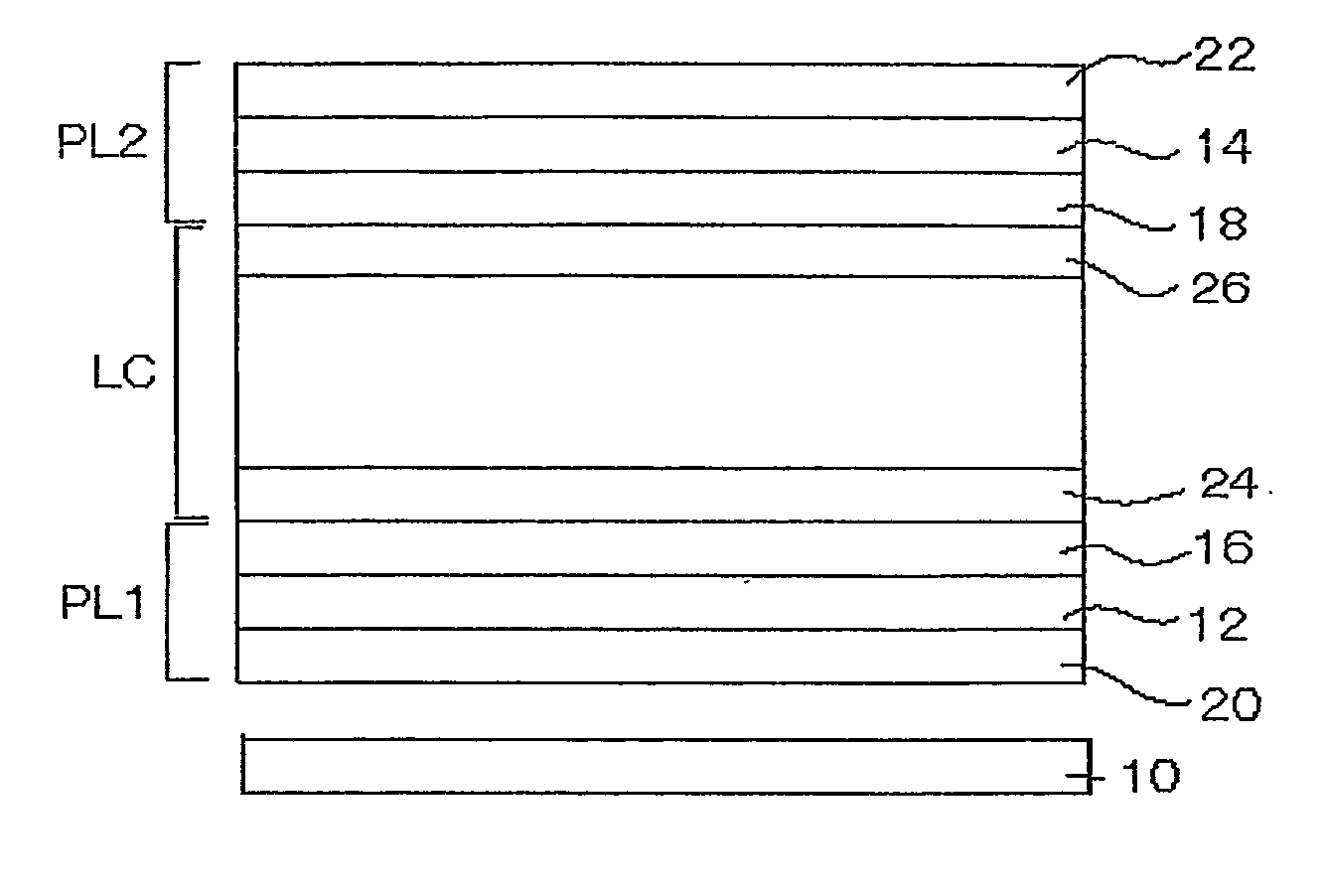
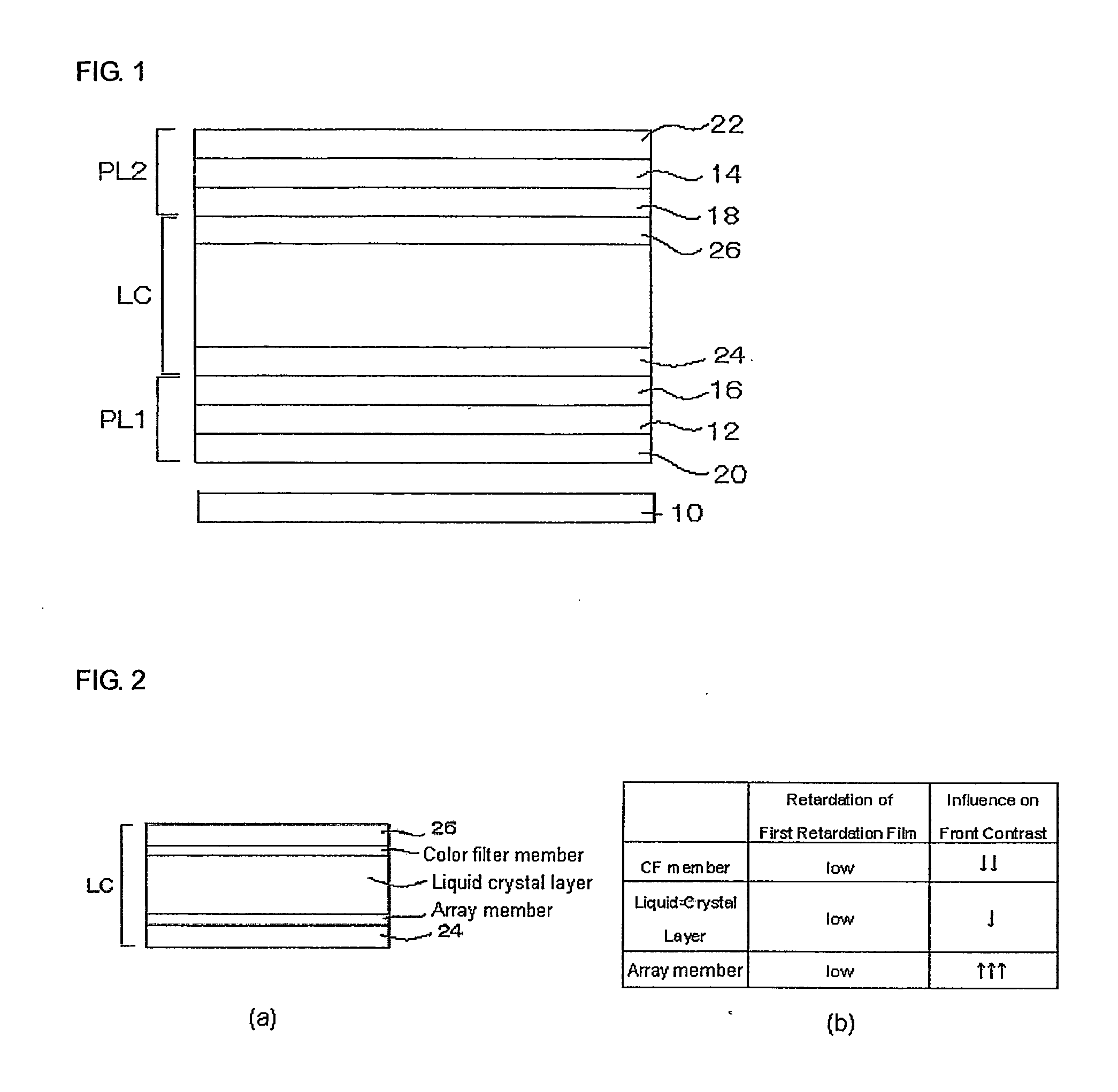
The present invention provides a VA-mode liquid-crystal display device with a high front contrast ratio. The invention achieves this by addressing the issue of reducing the front contrast ratio in high-CR liquid-crystal display devices. The invention proposes a first retardation region comprising one or more retardation layers between the rear-side polarizing element and the liquid-crystal cell, wherein the first retardation region satisfies the following formulae: 0 nm≦Re(590)≦10 nm, and |Rth(590)|≦25 nm. The invention also provides a second retardation region comprising one or more retardation layers between the front-side polarizing element and the VA-mode liquid-crystal cell, wherein the second retardation region satisfies the following formulae: 30 nm≦Re(590)≦90 nm, and 170 nm≦Rth(590)≦300 nm. The invention further proposes the use of a cellulose acylate film containing at least one compound that reduces retardation along the thickness direction, or a cellulose acylate film containing at least one compound capable of reducing both retardation in plane and retardation along the thickness direction. The use of these films can significantly improve the front contrast ratio of the liquid-crystal display device.

Problems solved by technology

For high-CR liquid-crystal display devices, it is difficult to further elevate the contrast ratio therein according to the techniques heretofore proposed based on the factors of CR reduction.

Method used


Image

  • Va mode liquid crystal display device
  • Va mode liquid crystal display device
  • Va mode liquid crystal display device

Examples


examples

[0169]The invention is described in more detail with reference to the following Examples. In the following Examples, the amount of the material, reagent and substance used, their ratio, the operation with them and the like may be suitably modified or changed not overstepping the sprit and the scope of the invention. Accordingly, the scope of the invention should not be limited to the following Examples.

1. Production of Films 1 to 6:

[0170]Cellulose acylates shown in the following Table were prepared, which differ in the type of the acyl group therein and in the degree of substitution with the acyl group. Concretely, a catalyst, sulfuric acid (in an amount of 7.8 parts by mass relative to 100 parts by mass of cellulose) was added to cellulose, and then a carboxylic acid to give the acyl group was added thereto, and the cellulose was acylated at 40° C. In this, the type and the amount of the carboxylic acid were changed to thereby change and control the type pf the acyl group and the d...


PUM

PropertyMeasurementUnit
thicknessaaaaaaaaaa
refractivity anisotropyaaaaaaaaaa
massaaaaaaaaaa

Abstract

The present invention relates to a VA-mode liquid-crystal display device comprising a front-side polarizing element (14), a rear-side polarizing element (12), a VA-mode liquid-crystal cell (LC) disposed between the front-side polarizing element and the rear-side polarizing element, and a first retardation region (16) comprising one or more retardation layers between the rear-side polarizing element and the VA-mode liquid-crystal cell, wherein the first retardation region satisfies 0 nm≦Re(590)≦10 nm, and |Rth(590)|≦25 nm. Re(λ) means retardation (nm) in plane at a wavelength λ nm, and Rth(λ) means retardation (nm) along the thickness direction at a wavelength λ nm.

Description

TECHNICAL FIELD[0001]The present invention relates to a VA (vertically aligned)-mode liquid-crystal display device improved in the front contrast ratio.BACKGROUND ART[0002]These days elevation of the contrast ratio (CR) in liquid-crystal display devices is being promoted. In particular, a VA-mode liquid-crystal display device has the advantage that CR in the normal direction (hereinafter referred to as “front CR”) is high as compared with that in other modes, and various studies and developments are now made for further enhancing the advantage. As a result, in these 6 years, the front CR in VA-mode liquid-crystal display devices has increased from about 400 to about 8000, or by about 20 times.[0003]On the other hand, in liquid-crystal display devices, it is important that not only the front CR is high but also CR in oblique directions (hereinafter this may be referred to as “viewing angle CR”) is high. Various techniques of using a retardation film have been proposed for reducing th...

Claims


Application Information

Patent Timeline
Patent Type & Authority Applications(United States)
IPC IPC(8): G02F1/13357G02F1/13363
CPCG02F1/133634G02F1/1393G02F2413/02G02F2413/05
Inventor ISHIGURO, MAKOTO
Owner FUJIFILM CORP
Learn More