Hybrid High-Pressure Low-Pressure EGR System

a high-pressure, hybrid technology, applied in the direction of combustion-air/fuel-air treatment, process and machine control, instruments, etc., can solve the problems of increasing nitrogen-oxide (nox) emissions of the engine, accelerating material ageing, and reducing combustion and exhaust temperatures. , to achieve the effect of increasing nitrogen-oxide (nox) emissions, accelerating material ageing, and high combustion and exhaust temperatures

Inactive Publication Date: 2011-06-09
FORD GLOBAL TECH LLC
View PDF17 Cites 33 Cited by
  • Summary
  • Abstract
  • Description
  • Claims
  • Application Information

AI Technical Summary

Benefits of technology

[0002]A boosted engine may exhibit higher combustion and exhaust temperatures than a naturally aspirated engine of similar output power. Such higher temperatures may cause increased nitrogen-oxide (NOX) emissions from the engine and may accelerate materials ageing, including exhaust-aftertreatment catalyst ageing. Exhaust-gas recirculation (EGR) is one approach for combating these effects. EGR works by diluting the intake air charge with exhaust gas, thereby reducing its oxygen content. When the resulting air-exhaust mixture is used in place of ordinary air to support combustion in the engine, lower combustion and exhaust temperatures result. EGR may also improve fuel economy in gasoline engines by reducing throttling losses and heat rejection.

Problems solved by technology

Such higher temperatures may cause increased nitrogen-oxide (NOX) emissions from the engine and may accelerate materials ageing, including exhaust-aftertreatment catalyst ageing.
When the resulting air-exhaust mixture is used in place of ordinary air to support combustion in the engine, lower combustion and exhaust temperatures result.
However, fully redundant HP and LP EGR systems can be heavy and expensive—each loop including conduits, heat-exchangers, control valves, and in some cases, flow sensors.
Further, fully redundant HP and LP EGR systems are typically unable to route exhaust gas from an HP take-off point to an LP mixing point, as may be desired under some operating conditions.

Method used


Image

  • Hybrid High-Pressure Low-Pressure EGR System
  • Hybrid High-Pressure Low-Pressure EGR System
  • Hybrid High-Pressure Low-Pressure EGR System

Examples


Embodiment Construction

[0024]The subject matter of this disclosure is now described by way of example and with reference to certain illustrated embodiments. Components that may be substantially the same in two or more embodiments are identified coordinately and are described with minimal repetition. It will be noted, however, that components identified coordinately in the different embodiments may be at least partly different. It will be further noted that the drawings included in this disclosure are schematic. Views of the illustrated embodiments are generally not drawn to scale; aspect ratios, feature size, and numbers of features may be purposely distorted to make selected features or relationships easier to see.

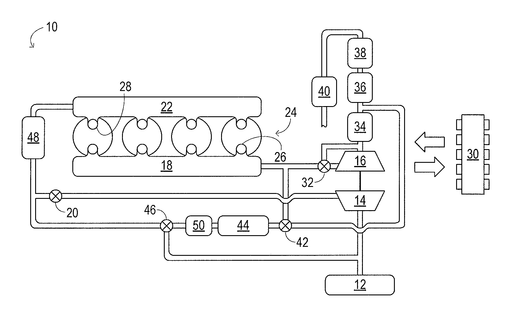
[0025]FIG. 1 schematically shows aspects of an example engine system 10 in one embodiment. In engine system 10, fresh air is inducted via air cleaner 12 and flows to compressor 14. The compressor is a turbocharger compressor mechanically coupled to turbine 16, the turbine driven by expanding en...


PUM


Abstract

An example system for inducting air into an engine includes a compressor and a turbine mechanically coupled to the compressor and driven by expanding engine exhaust. The system also includes a first conduit network configured to route some engine exhaust from a take-off point downstream of the turbine to a mixing point upstream of the compressor, and, a second conduit network configured to route some engine exhaust from a take-off point upstream of the turbine to a mixing point downstream of the compressor. The first and second conduit networks in the system have a shared conduit and a control valve configured to adjust an amount of engine exhaust flowing through the first conduit network and to adjust an amount of engine exhaust flowing through the second conduit network. The system also includes a flow sensor coupled in the shared conduit.

Description

TECHNICAL FIELD[0001]This application relates to the field of motor-vehicle engineering, and more particularly, to air induction and exhaust-gas recirculation in motor vehicle engine systems.BACKGROUND AND SUMMARY[0002]A boosted engine may exhibit higher combustion and exhaust temperatures than a naturally aspirated engine of similar output power. Such higher temperatures may cause increased nitrogen-oxide (NOX) emissions from the engine and may accelerate materials ageing, including exhaust-aftertreatment catalyst ageing. Exhaust-gas recirculation (EGR) is one approach for combating these effects. EGR works by diluting the intake air charge with exhaust gas, thereby reducing its oxygen content. When the resulting air-exhaust mixture is used in place of ordinary air to support combustion in the engine, lower combustion and exhaust temperatures result. EGR may also improve fuel economy in gasoline engines by reducing throttling losses and heat rejection.[0003]In boosted engine system...

Claims


Application Information

Patent Timeline
Patent Type & Authority Applications(United States)
IPC IPC(8): F02D23/00F02B33/44F01L1/34F02B47/08
CPCF02B33/38F02B37/04F02B37/18F02D9/16F02M25/0707F02M25/071Y02T10/121F02M25/0722F02M25/0732F02M25/0752F02M25/0798F02M35/10222F02M35/108F02M25/0718F02M35/112F02M26/01F02M26/05F02M26/07F02M26/15F02M26/19F02M26/24F02M26/51
Inventor STYLES, DANIEL JOSEPH
Owner FORD GLOBAL TECH LLC
Why Eureka
Try Eureka