
Apparatus for capacitively measuring changes

Active Publication Date: 2011-06-09
REIME GERD
View PDF5 Cites 17 Cited by
  • Summary
  • Abstract
  • Description
  • Claims
  • Application Information

AI Technical Summary

Benefits of technology

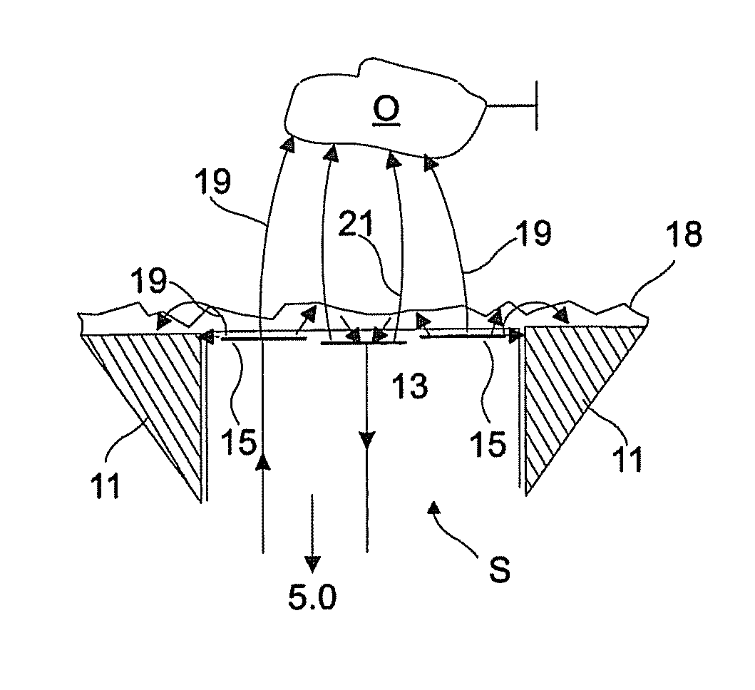
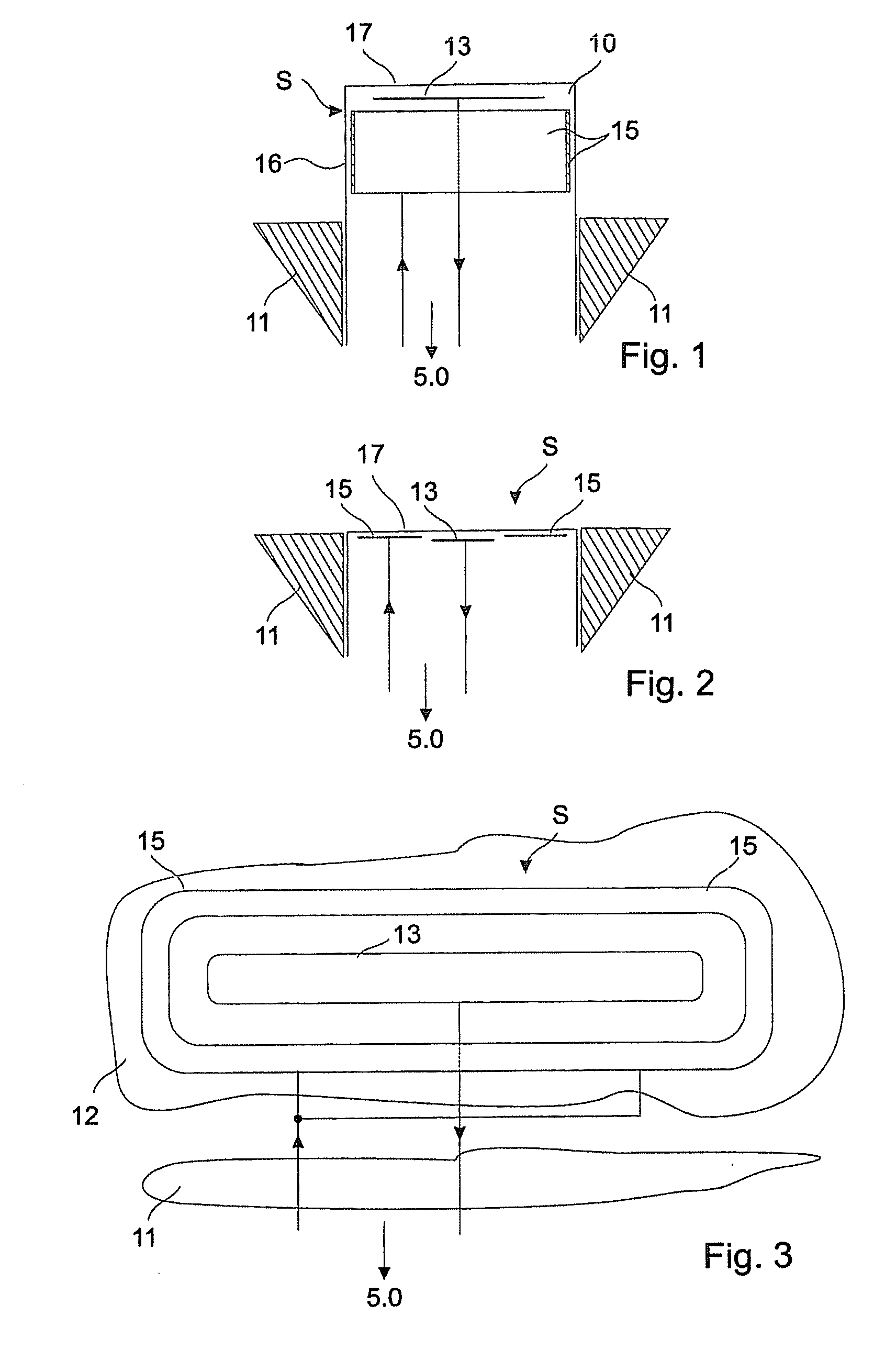
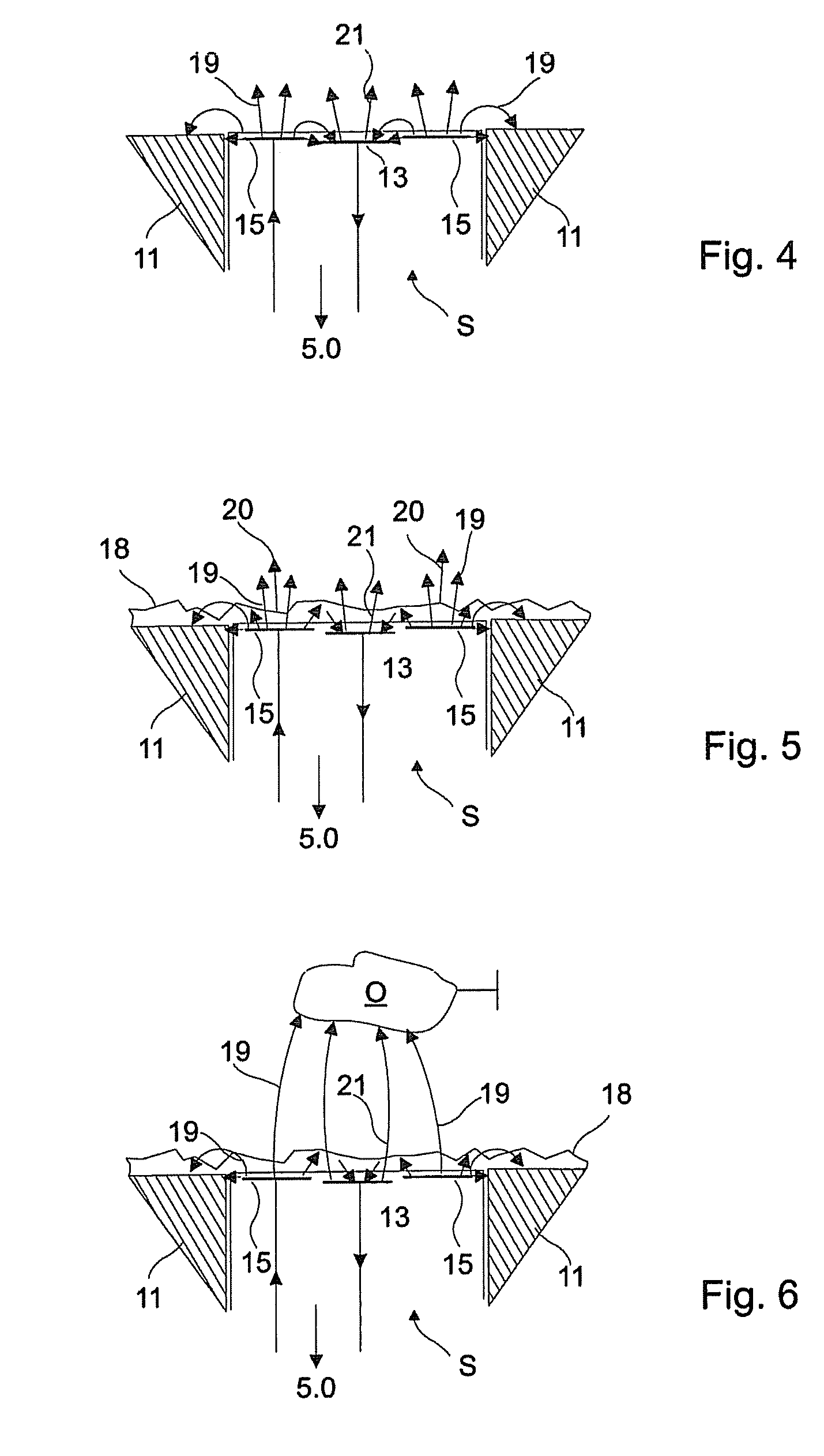
[0015]A sinusoidal or rectangular sensor signal of e.g. 100 kHz is applied to a first transmitting electrode and, due to the capacitive effect between the transmitting electrode and the further electrode, the further electrode is caused to adopt substantially the same electrical potential although it does this independently, i.e. not due to the fact that a screening electrode is caused to track the voltage of the transmitting electrode as in the state of the art. Both the transmitting electrode and the further electrode thus transmit a sensor signal. The further electrode is not fed by the control unit with a signal for the production of the electrical field. For the purposes of determining the capacitance of the further electrode with respect to earth, the weakening of this signal on the further electrode is determined. The spurious effects caused by wetting or contamination can be prevented by virtue of having a low impedance linkage of the first transmitting electrode to the driver stage of the driver / evaluation unit and the coupling of the magnetic field into possible coatings or wetted regions as well as by having a high impedance linkage of the further electrode to the evaluation system of the driver / evaluation unit.

Problems solved by technology

If, however, in an arrangement of this type an electrode is wetted with respect to a reference potential, e.g. a surrounding housing, then the electrical field is capacitively short circuited and it is no longer possible to detect changes in the surrounding field.
Consequently, the detection of a change resulting from the approach of an object is easily affected by other environmental influences.

Method used


Image

  • Apparatus for capacitively measuring changes
  • Apparatus for capacitively measuring changes
  • Apparatus for capacitively measuring changes

Examples


Embodiment Construction

[0029]The invention will now be described exemplarily in more detail with reference to the accompanying drawings. Nevertheless, the exemplary embodiments are only examples which are not intended to limit the inventive concept to a certain arrangement. Before the invention is described in detail, it should be pointed out that it is not restricted to the particular components of the device nor to the particular method steps, since these components and processes can vary. The terms used here are merely intended to describe special embodiments and are not used in a restrictive sense. If, moreover, the singular or indefinite articles are used in the description or in the Claims, these also refer to a plurality of these elements insofar as the general context does not make it unambiguously clear that something else is meant.

[0030]In the context of this application, the expressions “low impedance” and “high impedance” are used. A low impedance connection is present if the transmitting elec...


PUM


Abstract

An apparatus for capacitively measuring changes has a sensor (S) with a sensor-active region. The sensor has at least one transmitting electrode, which generates an electric field, and a further electrode (13) which is capacitively coupled to the transmitting electrode (15), wherein the transmitting electrode (15) is arranged between the further electrode (13) and an element (11) which is at a reference potential. An output of a driver / evaluation unit (5.0) is coupled to the transmitting electrode (15) and an input of the driver / evaluation unit (5.0) is coupled at high impedance to the further electrode (13), an electric field forming between the further electrode (13) and a reference potential on account of the electric field, generated by the transmitting electrode (15), between the transmitting electrode (15) and the further electrode (13). A change in the capacitance between the further electrode (13) and the reference potential is thus detected using the driver / evaluation unit (5.0). This provides a capacitive sensor which can be used to reliably detect changes in the sensor environment and is insensitive to a reference potential even in the case of a coating (18) or wetting (18).

Description

REFERENCE TO RELATED APPLICATIONS[0001]The present application claims the priority of the German patent application 10 2008 035 627.1, filed on 31 Jul. 2008, the published content of which is hereby expressly incorporated in the subject matter of the present application.TECHNICAL FIELD[0002]The invention relates to an apparatus for the capacitive measurement of changes within a sensor-active region of a sensor utilizing the production of an electrical field.BACKGROUND[0003]A capacitive distance sensing system is known from DE 40 06 119 C2. The system consists of a sensor or oscillator, respectively, a sending and a receiving capacitance, a demodulator and a switching amplifier. The oscillator comprises a condenser which can be externally influenced. An active electrode, a ground electrode and a screening electrode that is arranged between these two electrodes are associated with this condenser. The active electrode and the screening electrode are at the same electrical potential due...

Claims


Application Information

Patent Timeline
IPC IPC(8): G01R27/26
CPCH03K17/955H03K2217/960775H03K2217/96073H03K2017/9602H03K2217/960765
Inventor REIME, GERD
Owner REIME GERD
Learn More