Charge pump circuit

Inactive Publication Date: 2011-06-09
RENESAS ELECTRONICS CORP
View PDF6 Cites 23 Cited by
  • Summary
  • Abstract
  • Description
  • Claims
  • Application Information

AI Technical Summary

Benefits of technology

[0046]As described above, the first charge pump circuit and the second charge pump circuit alternately perform the boosting operations. A charging state of the capacitor of one of the first and second charge pump circuits is used for controlling the charging of the capacitor of the other thereof in the next period. The voltage applied to the switch is always less than the breakdown voltage of the switch, even if the number of stages of the capacitors and switch transistors is increased. It is therefore possible to make the charge pump output voltage larger than the e

Problems solved by technology

However, a circuit for controlling the gate control signal requires a high-voltage element, which results in increase in the circuit size.
Moreover, it is necessary to supply a constant current for controlling the gate control signal, which results in reduction in a boosti

Method used


Image

  • Charge pump circuit
  • Charge pump circuit
  • Charge pump circuit

Examples


Example

[0059]The invention will be now described herein with reference to illustrative embodiments. Those skilled in the art will recognize that many alternative embodiments can be accomplished using the teachings of the present invention and that the invention is not limited to the embodiments illustrated for explanatory purposed.

[0060](Configuration)

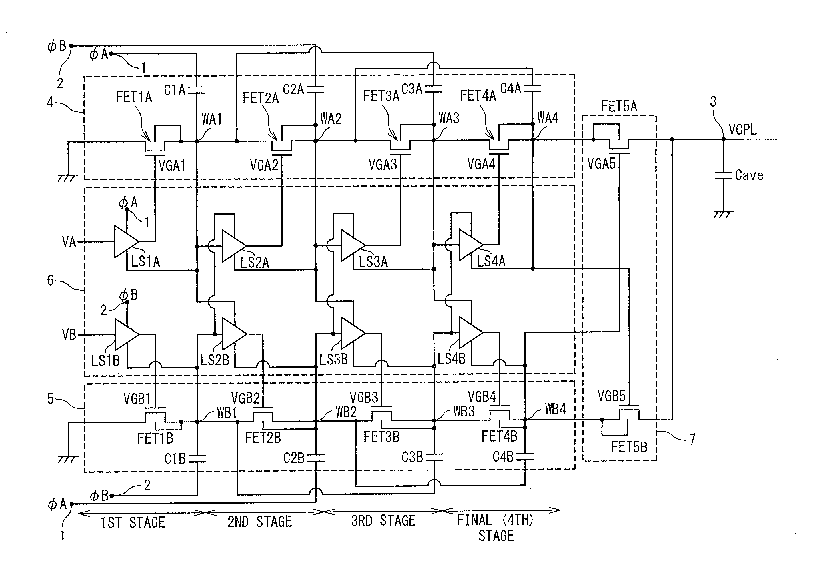
[0061]A configuration of a charge pump circuit according to an embodiment of the present invention will be described with reference to FIG. 6 and FIG. 7. FIG. 6 shows the configuration of the charge pump circuit according to the embodiment of the present invention. A four-stage negative voltage booster circuit will be described as an example of the charge pump circuit according to the embodiment of the present invention.

[0062]The charge pump circuit according to the embodiment of the present invention has: plural stages of first switches (FET1A, FET2A, FET3A and FET4A); plural stages of second switches (FET1B, FET2B, FET3B and FET4B); a third...


PUM


Abstract

A charge pump circuit has: first and second charge pump circuits alternately performing boosting operations; and a control circuit. The first (second) charge pump circuit has: plural stages of first (second) switch transistors connected in series; plural stages of first (second) connection nodes respectively connected to sources of the first (second) switch transistors; and plural stages of first (second) capacitors respectively connected to the first (second) connection nodes. The control circuit has: plural stages of first inverters and plural stages of second inverters. The n-th-stage first (second) inverter is supplied with a positive-side power supply voltage from the (n−1)-th-stage second (first) connection node, is supplied with a negative-side power supply voltage from the n-th-stage first (second) connection node, is supplied with an input voltage from the (n−1)-th-stage first (second) connection node, and outputs an output voltage to a gate of the n-th-stage first (second) switch transistor.

Description

INCORPORATION BY REFERENCE[0001]This application is based upon and claims the benefit of priority from Japanese patent application No. 2009-276856, filed on Dec. 4, 2009, the disclosure of which is incorporated herein in its entirety by reference.BACKGROUND OF THE INVENTION[0002]1. Field of the Invention[0003]The present invention relates to a charge pump circuit.[0004]2. Description of Related Art[0005]An electronic device operating by a low-voltage power supply such as a battery cell generally uses a booster circuit that boosts the low power supply voltage up to an operation voltage with which the electronic device can operate normally.[0006]One representative booster circuit is a charge pump-type booster circuit (hereinafter referred to as a charge pump circuit) that is configured by combining a plurality of diodes and a plurality of capacitors. The charge pump circuit is preferably used in a semiconductor integrated circuit.[0007]In the charge pump circuit, a pair of a diode and...

Claims


Application Information

Patent Timeline
IPC IPC(8): G05F1/10
CPCH02M2003/077H02M3/073H02M3/077
Inventor HONDA, YURI
Owner RENESAS ELECTRONICS CORP
Why Eureka
Try Eureka