[0018]An
advantage of the present invention is that it is not necessary to aim for a sharp
cut of the
adsorbed molecule species at the adsorption unit, but a portion of the N2 and O2 in the vent gas stream may also be adsorbed in the adsorbing material. When practically all CO2 and some of the N2 and O2 of the vent gas stream are adsorbed in the adsorption unit, practically all pollutants which may remain in the vent gas stream, especially
NOx and CO molecules, are typically also adsorbed in the adsorbing material. Thus, when the desorbed gas stream is conducted back to the furnace, also some N2 and O2 and all remaining pollutants, especially
NOx and CO molecules, are recycled back to the furnace.
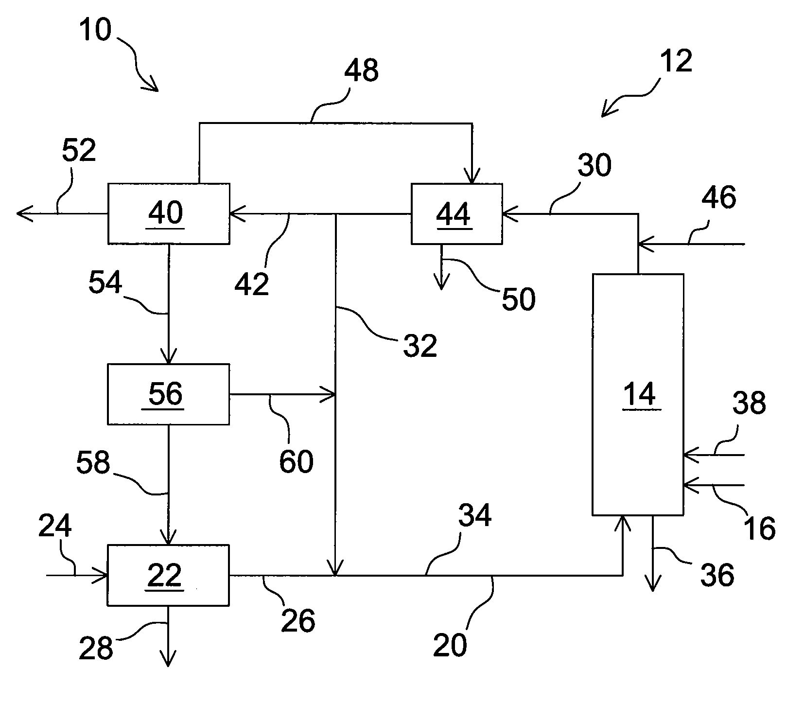
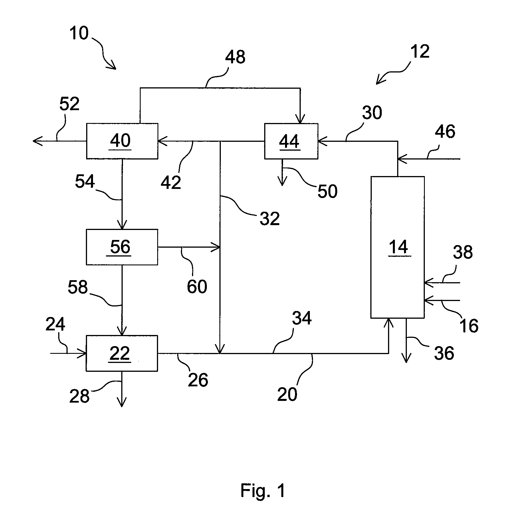
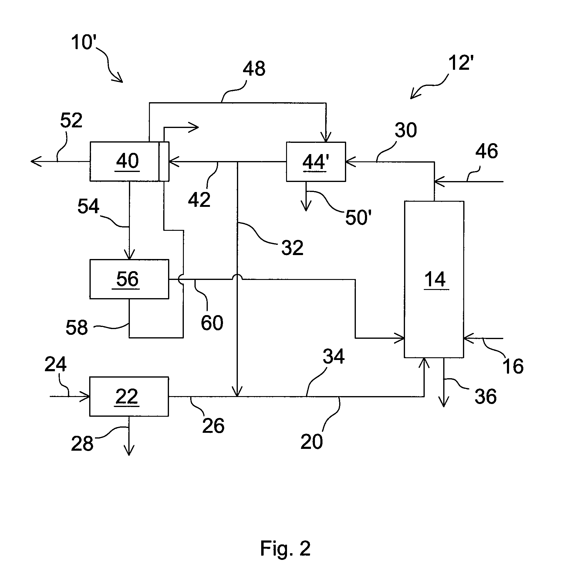
[0019]As described above, the combustion system forms two closed loops: direct recycling of the second portion of the exhaust gas and the recycling of the compounds desorbed from the adsorption unit, without releasing any emissions to the
atmosphere. As the
pollutant compounds are recycled back to the furnace, a portion of the compounds, especially CO, SO3 and
NOx molecules, as well as possible VOC-compounds (volatile organic compounds), are destructed in the furnace. The destructing of the
pollutant compounds is important because otherwise the
pollutant levels in the exhaust gas might increase to relatively high values before a balance is reached between the forming and capturing of the pollutants.
[0020]Due to the pollutant recycling, conventional NOx reducing processes of the combustion system function very effectively even without high NOx removal efficiency during a
single cycle. Therefore, it is possible to use relatively low NH3 / NOx ratio in a conventional NOx removing process. According to a preferred embodiment of the present invention, the
combustion process does not include any dedicated NOx reduction process, i.e., for example, a selective catalytic NOx reduction (SCR) or selective non-catalytic NOx reduction (SNCR) process. Correspondingly, according to a preferred embodiment of the present invention, the combustion system does not comprise any dedicated means for NOx reduction, i.e., for example, a NOx catalyst or means for selective non-catalytic NOx reduction. Reason for this is that any NOx in the vent gas from the CPU is efficiently adsorbed in the adsorption unit, and the NOx is desorbed and recycled back to the furnace. The recycled NOx is efficiently reduced to N2 in the furnace, which N2 will then eventually be separated by the adsorption unit to the pass through gas stream which is released to the
atmosphere, either directly or via the ASU. On the other hand, in order to avoid dissolving sulphur in the exhaust gas into the liquid CO2 stream discharged from the CPU unit, the combustion system advantageously comprises an efficient SOx capturing process, like a
scrubber, in the system.
[0021]When the adsorption unit adsorbs all the CO2 of the vent gas stream, it adsorbs in practice also some N2 and O2. At least when some zeolites are used for efficient adsorption of CO2, a considerable amount of N2 may also be adsorbed. In this case, the pass through gas stream may have a relatively high O2 concentration, and it forms a high quality feed gas to the ASU. The pass through gas stream fed from the adsorption unit to the ASU consists, in addition to N2 and O2, also some Ar. The ASU removes the N2 and separates O2 to be conducted to the furnace. The ASU usually leaves a portion of the Ar in the
product gas stream, and thus some accumulation of Ar in the circulating gas may result. In case Ar accumulation becomes a problem, it is possible to release at least a portion of the pass through gas to the atmosphere, or to modify the ASU to improve the Ar separation.
[0022]According to a most preferred embodiment of the present invention, the adsorbing material and / or operation conditions of the adsorption unit are selected in such a way that, simultaneously when CO2 is efficiently adsorbed, also clearly more O2 than N2 is adsorbed in the adsorbing material. Suitable material may be, for example,
activated carbon when used at suitable operating conditions. When using such an adsorption process, the pass through gas comprises mainly N2 and only a relatively small amount of O2. Thus, the pass through gas can especially in these conditions advantageously be released to the atmosphere instead of being used as a feed gas of the ASU.
[0023]In case the adsorption unit operates at a low temperature, the pass through gas is, before being released to the atmosphere, advantageously used as a
coolant in the CPU and / or a cryogenic ASU. In some cases it is also advantageous to use at least a portion of the desorbed gas stream as a
coolant of the inlet gas streams of one or more of the CPU and ASU, before it is conducted back to the furnace.

