
Structure for inhibiting back end of line damage from dicing and chip packaging interaction failures

a technology of back end line damage and interaction failure, which is applied in the direction of semiconductor devices, semiconductor/solid-state device details, electrical apparatus, etc., can solve the problems of chip failure, cracks that damage active areas of chips, and uneven density of the material of the dielectric layer, so as to reduce the dielectric constant of the sicoh dielectric material

Active Publication Date: 2011-06-16
GLOBALFOUNDRIES U S INC
View PDF19 Cites 22 Cited by
  • Summary
  • Abstract
  • Description
  • Claims
  • Application Information

AI Technical Summary

Benefits of technology

This solution effectively limits the propagation distance of flaws generated during dicing, preventing damage to the crackstop region and enhancing the robustness of chip edges against dicing and thermal stress-induced failures, thereby improving yield and reliability without reducing productivity or I / O density.

Problems solved by technology

Often the density of the material of the dielectric layers is not uniform throughout.
Because such metal structure are very thin, such cracks usually severely affect interconnect lines and vias causing fracture thereof resulting in chip failure since the external connections to chip elements have been broken.
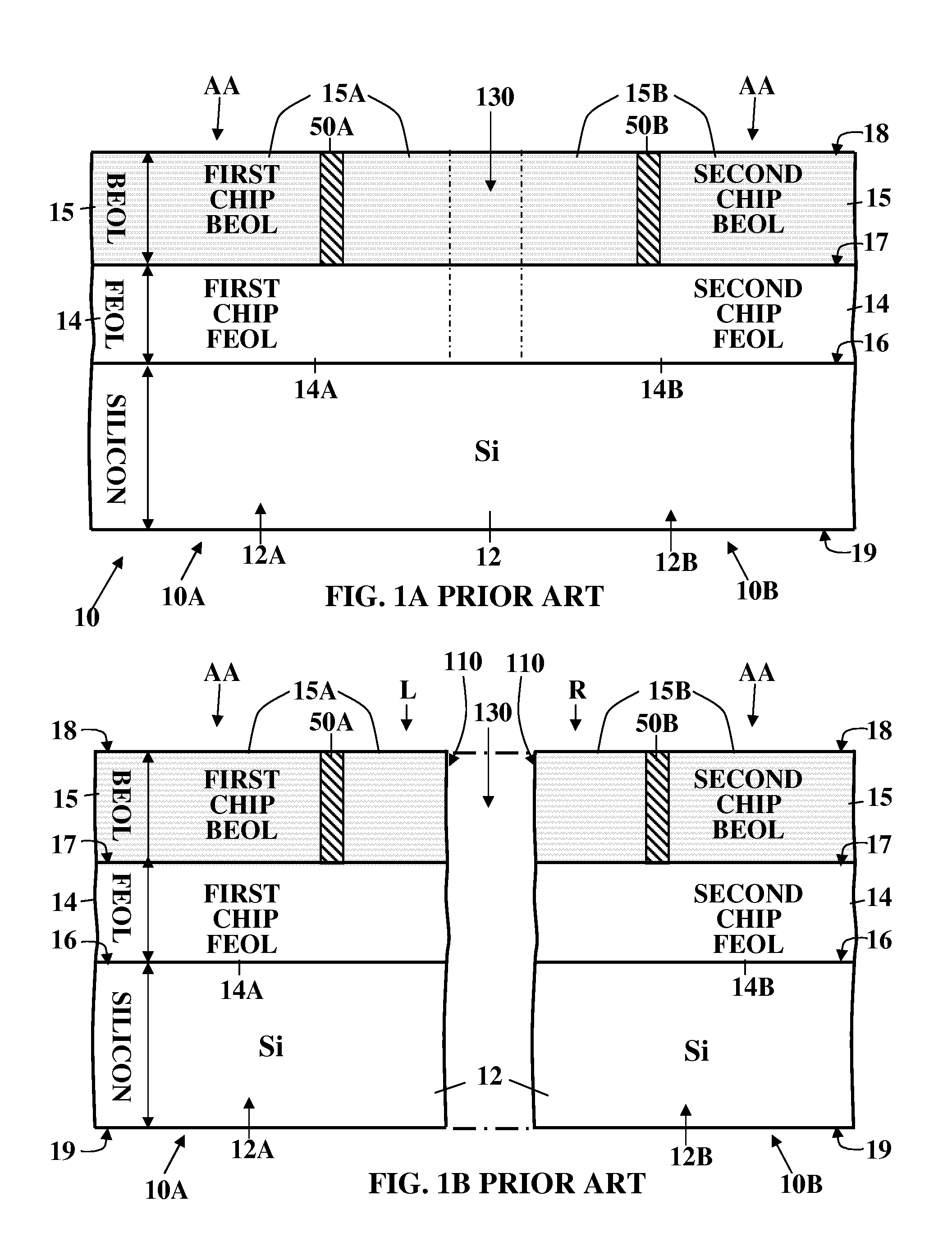
The dicing process often causes cracks that damage active areas of chips such as chips 10A / 10B.
Manifestly, the dicing process is destructive because it generates stresses and strains which often induce microcracks in the semiconductor substrate 12, the active device layer 14, and / or the dielectric layers in the interconnect layer 15.
As microcracks occur in a silicon substrate 12 they usually propagate very rapidly thereby causing failures that show up in the initial testing.
Microcracks in layers of dielectric material such as those found in the interconnect layers 15 propagate more slowly and tend to lead to delayed failures including chip packaging interaction fails, i.e. failures which occur after devices are in the field.
Chip packaging interaction failures, as well as failures in the field, are very expensive and disruptive.
As the number and complexity of chips per wafer increases, the yield often decreases proportionally.
However, as stated above, the problem with dicing of semiconductor devices is that the dicing process generates stresses and strains which can lead to cracking.
The dicing process often causes cracks that damage Active Areas (AA) of the chips.
Such cracking can damage the devices and metallization on the semiconductor chips.
Such dicing-initiated cracking can affect one or more of the many ILD layers in a BEOL structure 15, resulting in a loss of structural integrity.
Moreover, the problem is at its worst when the packaging substrate comprises an organic material as compared with a ceramic packaging substrate.
The delta value of the Coefficient of Thermal Expansion (CTE) mismatch between different assembled materials in the device being manufactured causes greater strains and stresses on the semiconductor chips, which, in turn, generate the growth of cracks within layers in a BEOL structure.
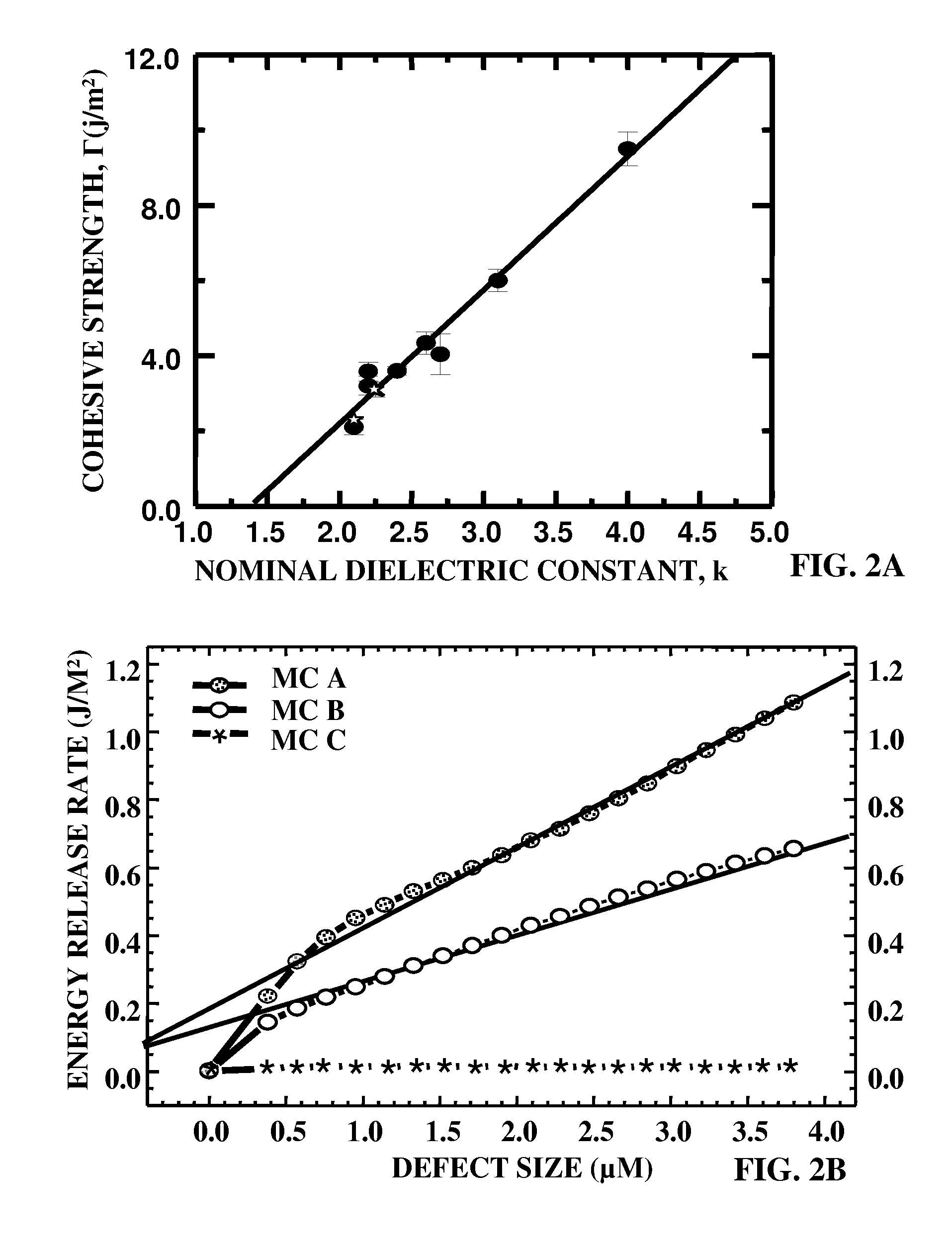
There is a problem, that the contemporary strategy of lowering of the cohesive strength of the ILD layer has resulted in the shifting of the location of the weakest material in an integrated structure from the substrate (which is typically monocrystalline silicon) to the ILD layers.
Thus, the result of the strategy of use of low-k materials in the ILD layer has introduced new failure mechanisms during the steps of dicing of wafers into chips and subsequent packaging and reliability testing.
While there are a number of potential solutions to this problem, in the past solutions which have been employed have required either a loss in productivity (reduction in number of chips per wafer) or a loss in I / O density due to a redesign of a Controlled Collapse Chip Connection (C4) layouts.
As the flaw extends to greater lengths, there is a monotonic increase in the energy release rate tending to drive the flaw towards failure.
Without the filler material, the rates of expansion and contraction would be different, resulting in potential joint failures, over time.
We have discovered that there is a problem that such a structure cannot prevent delaminations.
While there are a number of potential solutions to this problem, heretofore all solutions known require either a loss in productivity (reduction in number of chips per wafer) or a loss in I / O density (due to a redesign of a Controlled Collapse Chip Connection (C4) layout).

Method used


Image

  • Structure for inhibiting back end of line damage from dicing and chip packaging interaction failures
  • Structure for inhibiting back end of line damage from dicing and chip packaging interaction failures
  • Structure for inhibiting back end of line damage from dicing and chip packaging interaction failures

Examples


first preferred embodiment

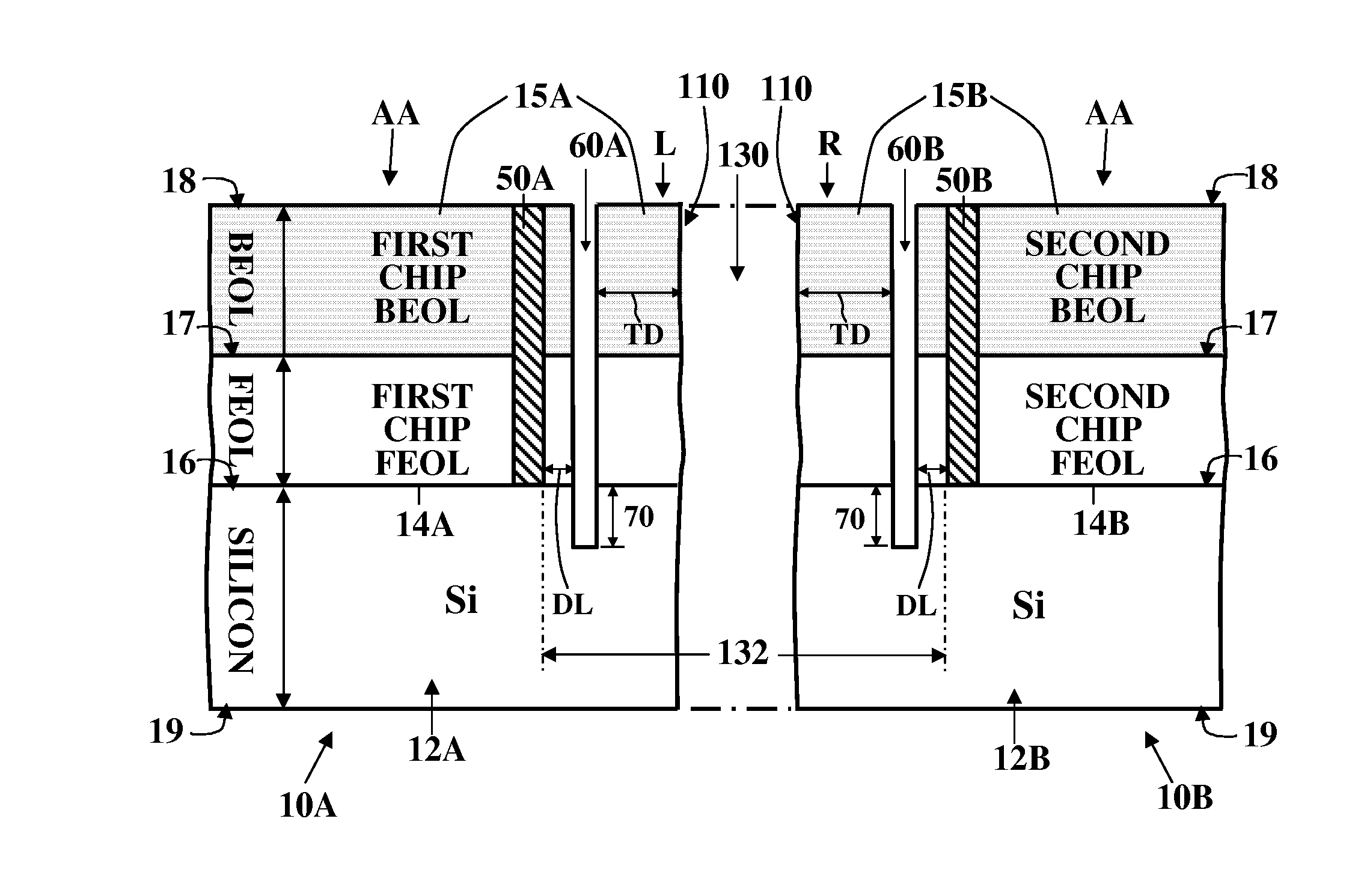
[0088]FIG. 5A is a sectional elevation, taken along line 5A-5A′ in FIG. 4, which shows an enlarged view of the second chip 10B after forming the UDIT 60B located between the edges 110 and the crackstops 50B; and after performing the dicing step in accordance with the process steps of FIG. 10A; but prior to forming an underfill layer 140. As is conventional, the silicon substrate 12B of the second chip 10B is lightly doped. A first FET 22B and a second FET 24B are shown schematically formed in the top surface of the active device layer 14B of the second chip 10B. There are metal interconnects (preferably copper conductors) in the form of horizontally extending metal lines 44 within several stacked dielectric layers 30 in the BEOL structure 15B. As will be well understood by those skilled in the art, the metal interconnects are connected together by the vertically extending metal vias 45. External connections are provided to the FET 22B by the combination of the metal interconnects 42...

second preferred embodiment

[0096]FIG. 6A shows the device of FIG. 5A with the outer margin 62 indented. i.e. recessed outboard from the UDIT trench between the UDIT trench 60B and the diced edge cut back, thereby forming a recessed region 62A of the BEOL structure 15B in the outer margin 62 thereof. In that portion of the outer margin 62 the interconnect layer 15B has been removed by means such as laser scribe, mechanical saw dicing or other such suitable methods so as to give the structure in FIG. 4 and the chip edge 110. Preferably the recessed region 62A which is located aside from the UDIT trench 60B′ and ILD region 30 has been formed by removing that portion of the BEOL structure 15B down to the top surface of the silicon substrate 12B by a laser ablation process.

[0097]FIG. 6B shows the semiconductor device 10B of FIG. 6A after deposition of the underfill layer 140 and after joining the device to a package 80. The underlayer 140 covers the top surface of the BEOL structure 15B and completely filling the ...

third preferred embodiment

[0098]FIGS. 7A, 7B and 7C show sectional views of a modification of the semiconductor device 10B of FIG. 5A in which a plurality of parallel UDIT trenches 60B, 61B and 62B have been formed, between the barrier structure 50B and the chip edge 110. FIG. 7B shows the semiconductor device 10B of FIG. 7A after deposition of the underfill layer 140 and after joining the device to a package 80. In the plan view of FIG. 7C, the narrow UDIT trenches 60B, 61B and 62B (which are of equal depth) surrounding the barrier structure 50B and the inner UDIT trenches have successively larger dimensions of length and width as shown in with widths as described above and where the area outside each trench may be intact or removed by previously described processes. An additional benefit of the chip edge in accordance with this invention may be realized once the chip is packaged which typically entails covering the chip with a molding compound (for a wirebond type application) or an underfill (for a C4 typ...


PUM

PropertyMeasurementUnit
dimensionsaaaaaaaaaa
perimeteraaaaaaaaaa
angleaaaaaaaaaa

Abstract

A semiconductor product comprises a semiconductor substrate having a top surface and a bottom surface including a semiconductor chip. The semiconductor substrate has a top surface and a perimeter. A barrier is formed in the chip within the perimeter. An Ultra Deep Isolation Trench (UDIT) is cut in the top surface of the chip extending down therein between the perimeter and the barrier. A ILD structure with low-k pSICOH dielectric and hard mask layers is formed over the substrate prior to forming the barrier and the UDIT. The ILD structure interconnection structures can be recessed down to the substrate aside from the UDIT.

Description

[0001]This application is a division of copending U.S. patent application Ser. No. 11 / 746,684 filed 10 May 2007, entitled “Inhibiting Damage From Dicing and Chip Packaging Interaction Failures in Back End of Line Structures”BACKGROUND OF THE INVENTION[0002]The present invention relates to Integrated Circuit (IC) semiconductor devices and structures and methods of manufacture thereof. More particularly it relates to structural features adapted to prevent of damage to semiconductor devices caused by subdivision of semiconductor wafers into individual chips by a process known as dicing. In addition, this invention relates to prevention of chip packaging interaction fails in interconnect structures formed during Back End Of Line (BEOL), interconnect, processing of semiconductor devices, late in the manufacturing process.[0003]Microelectronic semiconductor IC devices such as Complementary Metal Oxide Semiconductor Field Effect Transistor (CMOS FET) devices and the like are manufactured i...

Claims


Application Information

Patent Timeline
Patent Type & Authority Applications(United States)
IPC IPC(8): H01L23/58
CPCH01L21/563H01L21/78H01L2924/10253H01L23/5329H01L23/562H01L23/585H01L24/90H01L29/0657H01L2224/73203H01L2224/90H01L2924/01079H01L2924/18301H01L2924/01019H01L2924/13091H01L2924/00H01L2924/14H01L21/30
Inventor LANE, MICHAEL W.LIU, XIAO HUSHAW, THOMAS M.FAROOQ, MUKTA G.HANNON, ROBERTMELVILLE, IAN D.W.
Owner GLOBALFOUNDRIES U S INC
Learn More