This helps you quickly interpret patents by identifying the three key elements:
Problems solved by technology
Method used
Benefits of technology
Benefits of technology
[0067]In the invention claimed in Claim 1, incoming light (return light) is separated into two beams of light whose intensity changes complementarily in accordance with a change in the physical quantity of a measurement target object. Information on the physical quantity of the measurement target object is detected on the basis of a ratio of the intensity of one of the two beams of light and the intensity of the other, thereby offsetting the effects of measurement noise factors other than the physical-quantity attribute of the measurement target object, for example, twists in an optical fiber. Therefore, it is possible to carry out measurement with high precision.
[0082]In the invention claimed in Claim 16, a single light receiving section receives two separated beams of light. Since measurement accuracy is not influenced by a difference in the characteristics of a plurality of photo detectors, it is possible to carry out measurement with high precision.
Problems solved by technology
However, the following measurement noise factors other than the physical-quantity attribute of a measurement target object could have an influence on measurement accuracy, making it impossible to measure the physical quantity of the measurement target object with high precision: the effects of the emission power of a light source, fiber insertion loss, fluctuations in the sensitivity of a photo detector, fluctuations in the amplitude of an amplifier or other fluctuations, the loss of optical energy due to the bending of an optical fiber (bending loss), the loss of optical energy due to the connecting of two or more optical fibers by means of connectors (connector loss), the gain fluctuations of electric circuitry provided on a platform, and so forth.
Method used
Image
Click on the blue label to locate the original text in one second.
Reading with bidirectional positioning of images and text.
Examples
first embodiment
[0130]First of all, a first embodiment of the present invention will now be explained with reference to drawings.
(Overall Configuration)
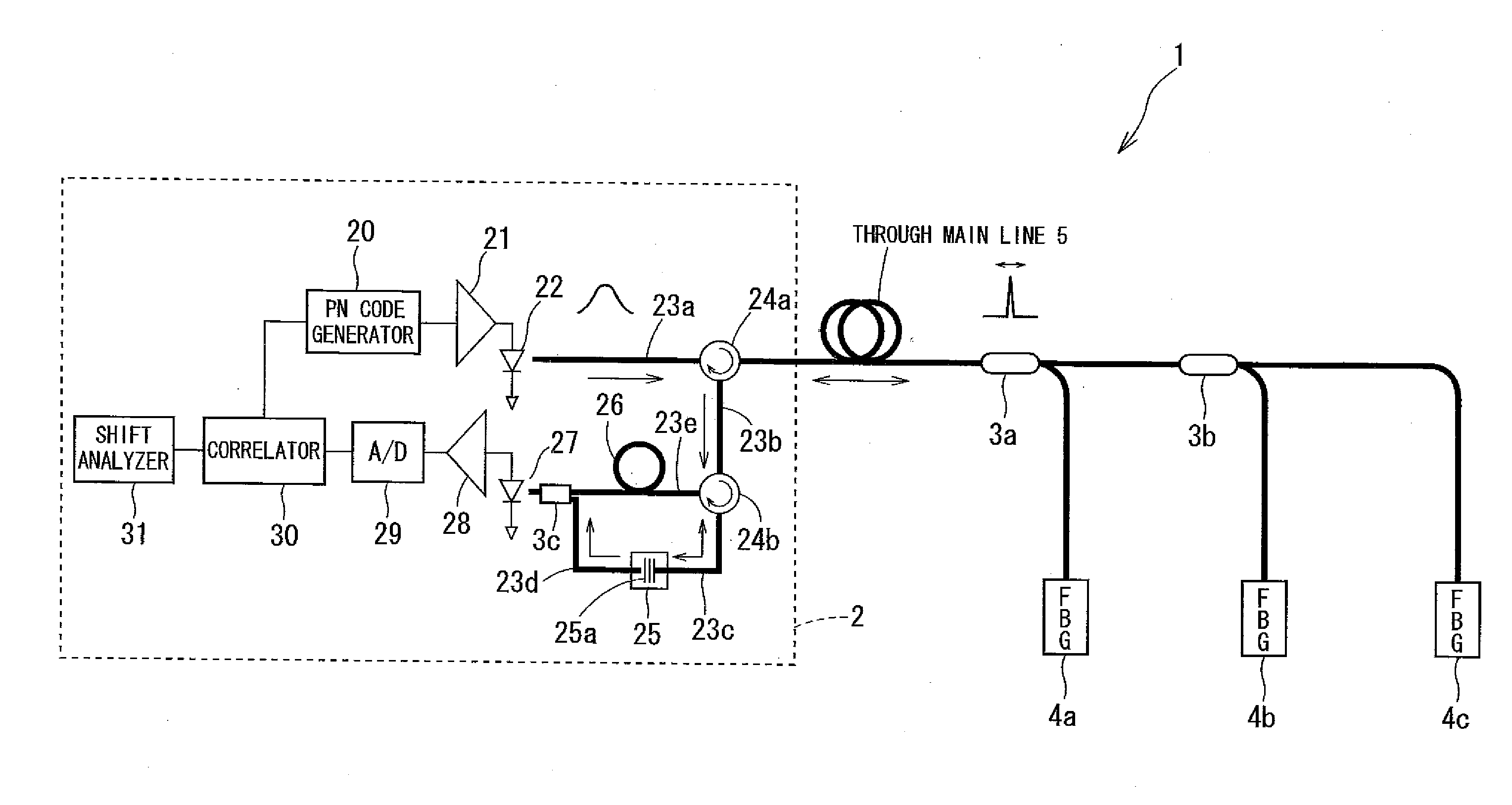
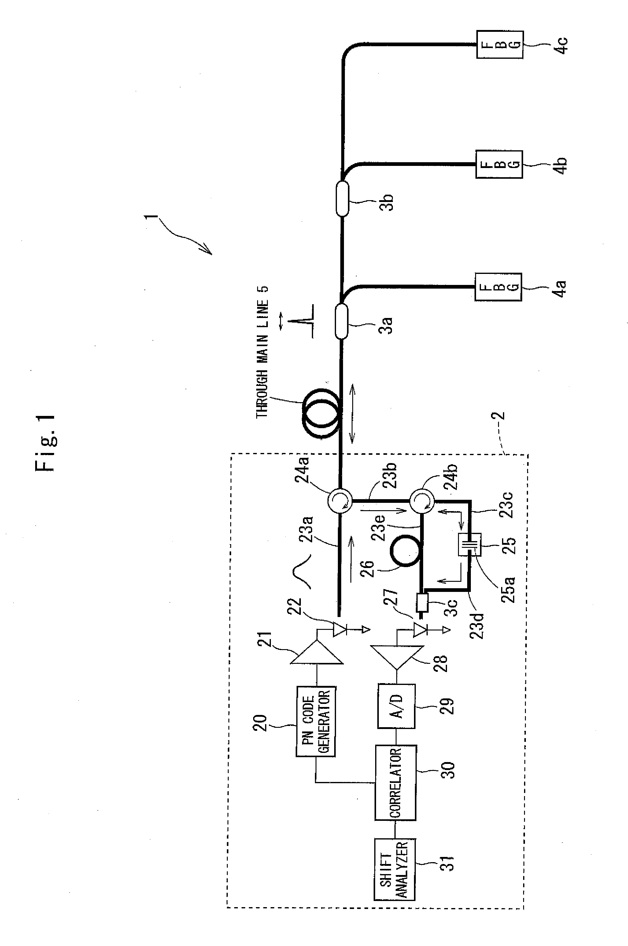
[0131]FIG. 1 is a diagram that illustrates the overall configuration of an optical fiber sensingsystem according to a first embodiment of the invention.
[0132]As illustrated in FIG. 1, an optical fiber sensingsystem 1 includes a measurement apparatus 2, optical couplers 3a and 3b, and FBGs 4a, 4b, and 4c, etc. The two optical couplers 3a and 3b are inserted on a through main line 5. The FBGs 4a and 4b are connected to the ends of respective branch lines, which branch at the optical couplers 3a and 3b from the through main line 5. The FBG 4c is connected to the end of the through main line 5.
[0133]The measurement apparatus 2 includes a PN code generator 20, a light source driver 21, a broadband light source 22, optical fibers 23a, 23b, 23c, 23d, and 23e, circulators 24a and 24b, a temperature control mechanism 25, a wavelength tilt filter 25a, a dum...
example 1
[0286]Next, as a specific example of a reflective sensor unit, a position change sensor unit 130 that is used for detecting a change in position (shift, displacement) as information on the physical quantity of a measurement target object will now be explained.
[0287]FIG. 24 is a diagram that illustrates the configuration of the position change sensor unit 130.
[0288]As illustrated in FIG. 24, the position change sensor unit 130 includes an optical coupler 131, an optical fiber collimating system 132, a dummy fiber 133, an isolator 134, etc.
[0289]The optical fiber collimating system 132 includes lenses 132a and 132b, which are aspherical opposed lenses (or rod opposed lenses), a transparent plate 132c, which is made of a borosilicate crown optical glass, a reflector plate 132d, which is made of a borosilicate crown optical glass with gold vapor deposition (or multilayer vapor deposition), etc. The transparent plate 132c and the reflector plate 132d are oriented perpendicular to the dir...
example 2
[0353]Next, a second example according to the present embodiment of the invention will now be explained.
[0354]In this example, a temperature-sensing reflective sensor unit that is used for detecting temperature information as information on the physical quantity of a measurement target object is described.
[0355]FIG. 39 is a diagram that illustrates the configuration of a temperature sensor unit 230, which is a temperature-sensing reflective sensor unit.
[0356]As illustrated in FIG. 39, the temperature sensor unit 230 includes an optical coupler 231, a reflecting system 232, a dummy fiber 233, the isolator 134, etc.
[0357]The reflecting system 232 includes a first ferrule 232a, a sleeve 232b, a second ferrule 232d, etc.
[0358]A dielectric multilayer film is vapor-deposited on an end face of the second ferrule 232d as a tilt filter 232c. As the reflection property of the tilt filter 232c, its reflection factor changes as the temperature of a measurement target object changes.
[0359]Next, ...
PUM
Abstract
Provided is an optical fibersensing system that can carry out measurement accurately without being affected by measurement noise factors other than the physical-quantity attribute of a measurement target object, for example, the effects of the emission power of a light source, fiberinsertion loss, fluctuations in the sensitivity of a photo detector, fluctuations in the amplitude of an amplifier or other fluctuations, the loss of optical energy due to the bending of an optical fiber (bending loss), the loss of optical energy due to the connecting of two or more optical fibers by means of connectors (connector loss), the gain fluctuations of electric circuitry provided on a platform, and so forth. A reflective sensor is connected to an end of an optical fiber connected to a light source. The light source outputs physical measurement light. Reflected light coming from the reflective sensor is separated into two beams of light. Information on the physical quantity of a measurement target object is detected on the basis of an intensity ratio of the two beams.
Description
TECHNICAL FIELD[0001]The present invention relates to an optical fiber sensingsystem that measures the physical quantity of a measurement target object with the use of an optical fiber.BACKGROUND ART[0002]Recently, a method of using an optical fiber as a sensor for detecting, for example, ground deformation, the distortion or deformation of a structure, etc., has been proposed. An example of such a method is FBG (Fiber Bragg Grating).[0003]In the FBG method, an ultravioletlaser beam is applied to a specified core region of an optical fiber for cyclic refractive index modulation in the direction of the length of the fiber. As its optical property, it exclusively reflects light in a specified spectral range in sync with the cycle, whereas light having any other wavelength is allowed to pass therethrough. The FBG method utilizes such optical property.[0004]If external pressure is applied to the region irradiated with the ultravioletlaser beam, or if ambient temperature changes, the ...
Claims
Application Information
Patent Timeline
Application Date:The date an application was filed.
Publication Date:The date a patent or application was officially published.
First Publication Date:The earliest publication date of a patent with the same application number.
Issue Date:Publication date of the patent grant document.
PCT Entry Date:The Entry date of PCT National Phase.
Estimated Expiry Date:The statutory expiry date of a patent right according to the Patent Law, and it is the longest term of protection that the patent right can achieve without the termination of the patent right due to other reasons(Term extension factor has been taken into account ).
Invalid Date:Actual expiry date is based on effective date or publication date of legal transaction data of invalid patent.

