
Method and system for stable and tunable high power pulsed laser system

a laser system and high-power technology, applied in laser details, metal-working apparatuses, domestic vessels, etc., can solve the problems of reducing the efficiency of harmonic generation using frequency doubling, difficult to achieve a range of variable pulse characteristics, and difficult to achieve a wide range of pulse characteristics. , to achieve the effect of broader applicability

Inactive Publication Date: 2011-06-16
ELECTRO SCI IND INC
View PDF36 Cites 25 Cited by
  • Summary
  • Abstract
  • Description
  • Claims
  • Application Information

AI Technical Summary

Benefits of technology

[0004]According to the present invention, methods and systems related to the field of tunable laser sources are provided. More particularly, the present invention relates to a method and apparatus for providing high power pulsed laser sources useful for industrial applications such as trimming, marking, cutting, and welding. Merely by way of example, the invention has been applied to a laser source with real-time tunable characteristics including pulse width, peak power, repetition rate, temporal pulse shape, polarization, wavelength, and / or spectral linewidth. However, the present invention has broader applicability and can be applied to other laser sources.
[0007]According to an alternative embodiment of the present invention, a method for providing amplified and stabilized laser pulses is provided. The method includes providing an optical radiation signal from an injection laser source and stabilizing a tunable pulsed source based on the optical radiation signal to produce stabilized signal pulses. The method also includes amplifying the stabilized signal pulses in an optical fiber amplifier and outputting the amplified and stabilized signal pulses.

Problems solved by technology

As such, the characteristics of such laser pulses cannot generally be varied in the field without compromising the laser performance.
Using such lasers, it is generally difficult to achieve a range of variable pulse characteristics.
One undesirable result of such broadened linewidth is to significantly reduce the efficiency of the harmonics generation using frequency doubling, tripling, and the like.

Method used


Image

  • Method and system for stable and tunable high power pulsed laser system
  • Method and system for stable and tunable high power pulsed laser system
  • Method and system for stable and tunable high power pulsed laser system

Examples


Embodiment Construction

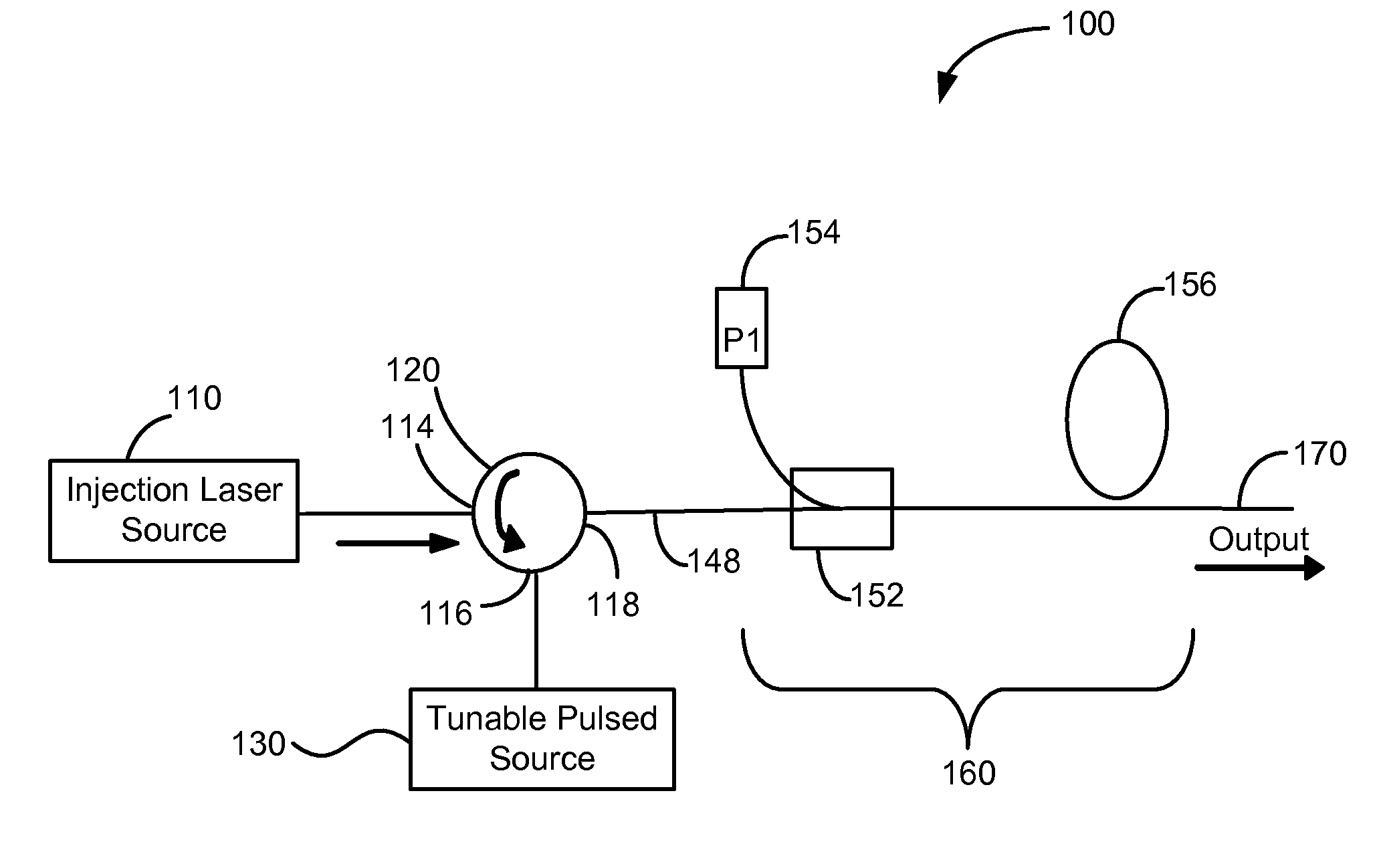
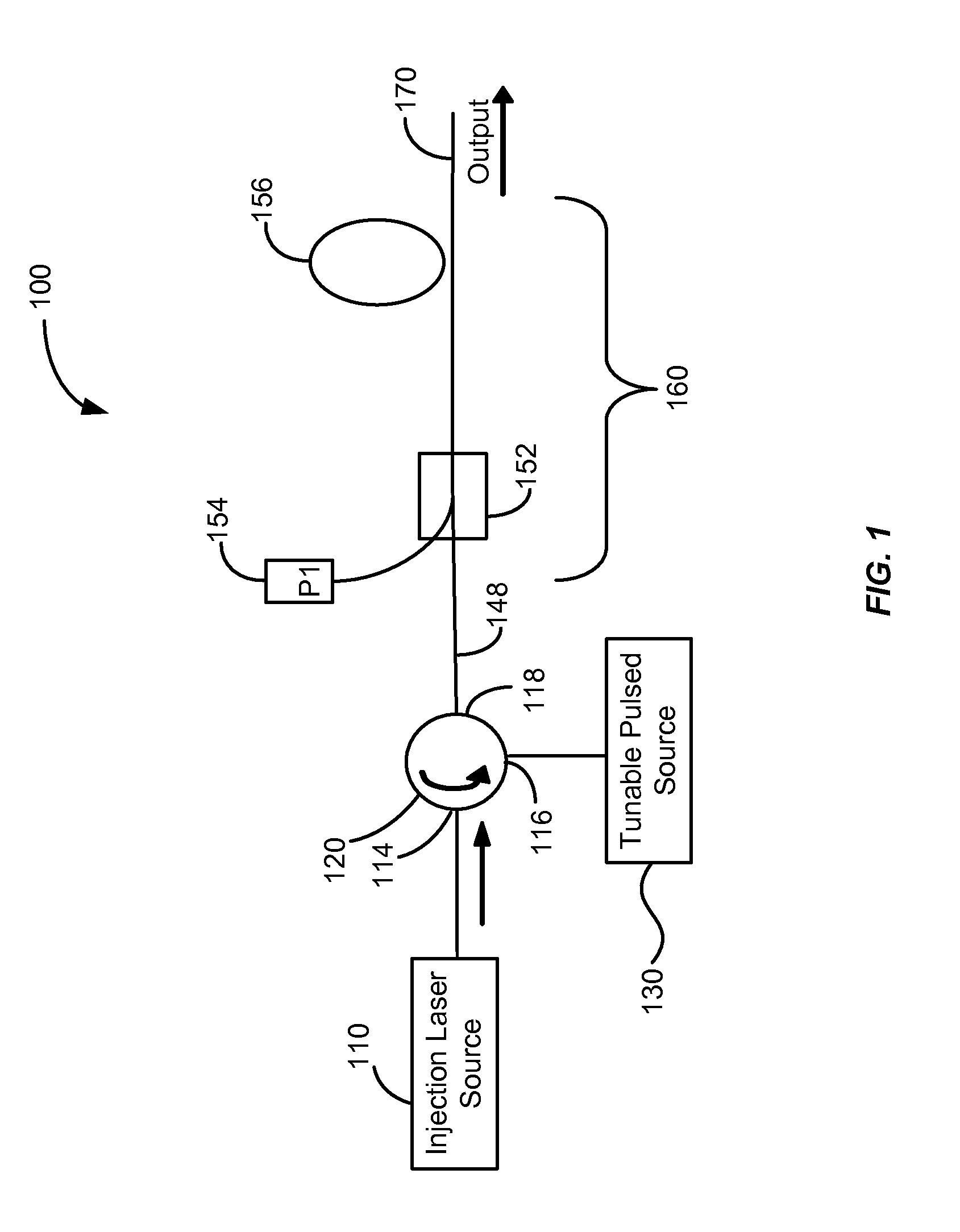
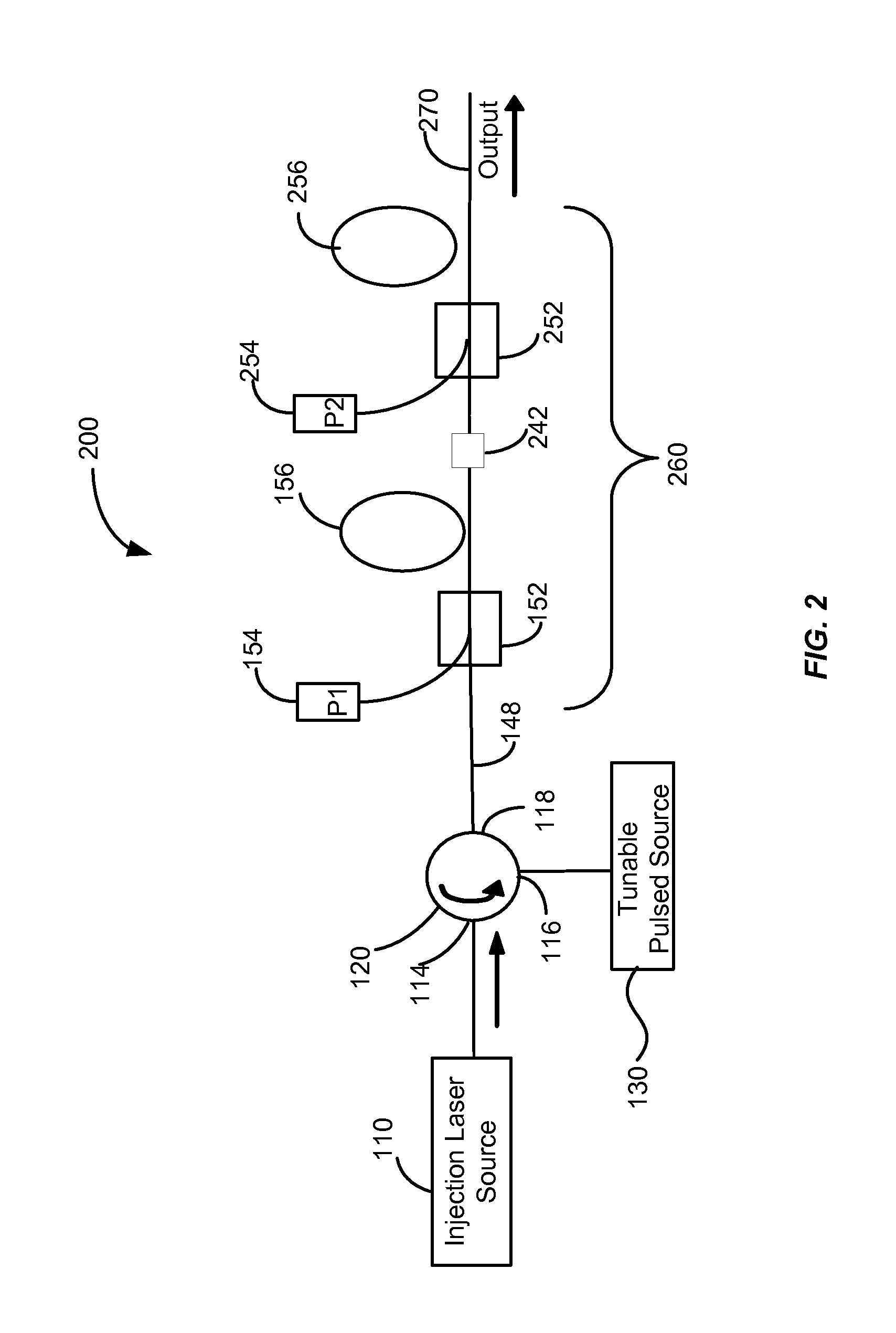
[0029]FIG. 1 is a simplified schematic illustration of a high power pulsed laser system with tunable pulse characteristics using an optical fiber amplifier according to an embodiment of the present invention. High power stabilized pulsed laser 100 includes an injection laser source 110 that generates stabilizing optical radiation, which is injected into a first port 114 of an optical combiner 120 and transmitted to a second port 116 of the optical combiner 120. In one embodiment, the combiner can be a circulator having three or more ports. Such a circulators is available as model OC-3-1064-PM from OFR, Inc. of Caldwell, N.J. According to an embodiment of the present invention, the stabilizing optical radiation is generated by using the injection laser source 110, also referred to as a stabilizing source, that is a continuous wave (CW) semiconductor laser.

[0030]In one embodiment, the injection laser source 110 includes a Fiber Bragg Grating (FBG) stabilized semiconductor diode laser ...


PUM

PropertyMeasurementUnit
front facet reflectivityaaaaaaaaaa
reflectivityaaaaaaaaaa

Abstract

A laser system includes an injection laser source having an output and operable to provide a laser output characterized by a first wavelength, a first linewidth, an output power. The laser system also includes a tunable pulsed source characterized by a gain bandwidth. The tunable pulsed source is operable to provide an output signal having an average power. The output signal includes a plurality of optical pulses. Each of the plurality of optical pulses is characterized by a second wavelength, a second linewidth, and a peak power. The laser system further includes an optical combiner having a first port coupled to the output of the injection laser source, a second port coupled to the tunable pulsed source, and a third port.

Description

CROSS-REFERENCES TO RELATED APPLICATIONS[0001]This application claims priority to U.S. Provisional Patent Application No. 61 / 186,317, filed on Jun. 11, 2009, entitled “Stable Tunable High Power Pulsed Laser Source,” the disclosure of which is hereby incorporated by reference in its entirety for all purposes.BACKGROUND OF THE INVENTION[0002]Pulsed laser sources, such as Nd:YAG lasers, have been used to perform laser-based material processing for applications such as marking, engraving, micro-machining, and cutting. Many existing high power pulsed lasers that are characterized by pulse energies greater than 0.5 mJ per pulse, rely on techniques such as Q-switching and mode locking to generate optical pulses. However, such lasers produce optical pulses with characteristics that are predetermined by the cavity geometry, the mirror reflectivities, and the like. As such, the characteristics of such laser pulses cannot generally be varied in the field without compromising the laser performa...

Claims


Application Information

Patent Timeline
Patent Type & Authority Applications(United States)
IPC IPC(8): H01S3/10
CPCH01S3/06754H01S3/0092H01S5/146H01S5/4006B23K26/032B23K26/063B23K26/1405B23K26/16B23K26/381B23K26/401B23K26/402B23K26/4065B23K26/407B23K26/409B23K2201/10B23K2201/12B23K2201/42H05K3/0038H01S3/06758H01S3/09415H01S3/10007H01S3/10015H01S3/1618H01S3/2375H01S5/005H01S5/0078H01S5/5018H01S5/06216B23K26/40B23K26/0622B23K26/142B23K26/382B23K2101/10B23K2101/12B23K2101/34B23K2101/42B23K2103/10B23K2103/12B23K2103/172B23K2103/42B23K2103/50B23K2103/54C03C2218/328H01S2301/02H01S2301/03H01S3/1001
Inventor REID, BENOITPANARELLO, TULLIOCAPLETTE, STEPHANE
Owner ELECTRO SCI IND INC
Learn More