Lightguide illuminator embedded display

a technology of lightguide and illuminator, applied in the field of slim form factor display, can solve the problems of reducing display system contrast, reducing volume requirements and thickness of display system, and reducing display system brightness, so as to limit fresnel reflection, increase display brightness, and maintain display performance

Inactive Publication Date: 2011-06-23
POWELL KARLTON DAVID +1
View PDF1 Cites 121 Cited by
  • Summary
  • Abstract
  • Description
  • Claims
  • Application Information

AI Technical Summary

Benefits of technology

[0025]By further adding a low refractive index optically transparent cladding layer on the outer viewing surfaces of the lightguide illuminator embedded display, optical performance of the display can be maintained when it is placed in a dirty environment. The cladding serves to maintain guiding of the light by maintaining critical angle at all positions across the lightguide illuminator so that extraction of light from the lightguide illuminator due to presence of beads of water or oil on the external surfaces of the lightguide illuminator does not occur. Cladding layers can be used in conjunction with two or more lightguide illuminator embedded displays in order to provide a three-dimensional (3-D) display. In such case of 3-D display, the low refractive index of the cladding layer, such as an air gap or a low-index optical media, serves to provide optical isolation of the lightguiding capability of each lightguide illuminator embedded display. If an air gap is used for optical isolation of the lightguide illuminator embedded displays, an anti-reflection coating can be applied to the outer surfaces of each lightguide illuminator embedded display in order to limit Fresnel reflections from either light transmitted from adjacent displays or from ambient light surrounding the display.
[0026]The inventors have discovered that by noting fold symmetry in a lightguide illuminator embedded display, a non-see-through lightguide illuminator embedded display can be formed by placing a reflective layer on or substantially near one side of the display layer, the side opposing the lightguide illuminator. The reflective layer reflectivity can be a broadband reflector or can be wavelength sensitive or partially reflective. In such case, the display is similarly embedded within the guiding of the lightguide illuminator, but any light that illuminates a diffusing pixel or region and is scattered in such a way that escapes TIR on the display side having the added reflective layer is reflected back into the display layer and rescattered, thus increasing brightness of the display toward the viewing side of the non-see-through lightguide illuminator embedded display.

Problems solved by technology

Typical fluorescent backlights, such as cold-cathode fluorescent (CCFL), have high voltage requirements and relatively short lifespans.
In addition, much of the light from fluorescent backlighting exhibits high angular frequencies that can contribute to scatter, potentially reducing display system contrast.
For a frontlight, arrays of sources typically cannot be placed directly in front of the display panel, since these sources are not transparent, and thus would block the display content from the viewer, so sources are typically placed significantly in front of the display, further increasing the volume requirements and thickness of the display system.
In addition, such type displays may require considerable control of the backlight angular subtense of light to avoid content overlap and screen to screen crosstalk issues when viewing at higher viewing angles.
A disadvantage of this embodiment is that a projector is required in order to provide backlight to the volumetric display layers, thus substantially increasing system thickness.
The requirement of a transparent substrate and a light guide on the transparent substrate side of the liquid crystal element increases complexity of the display system unnecessarily as it requires two distinct substrates in order to provide functionality.
In addition, while a lamp may provide adequate uniformity as a light source for small display form factors, applications requiring large area, thin form factor displays may suffer disadvantage when not using an array of light sources, such as in the case of using LEDs.
However, this invention requires multiple light-emitting surfaces of prisms having grooves, and thus may exhibit too high a level of complexity as well as cost for large area and low cost display systems requiring a double-sided backlight.

Method used


Image

  • Lightguide illuminator embedded display
  • Lightguide illuminator embedded display
  • Lightguide illuminator embedded display

Examples


Embodiment Construction

[0039]The following Detailed Description further describes concepts and discloses specific details of the preferred embodiments in order to provide a thorough understanding of claimed subject matter. However, those skilled in the art will understand that the claimed subject matter may be practiced without these specific details. In other instances, the description may not describe in detail well-known methods, processes, procedures, components and / or sub-components.

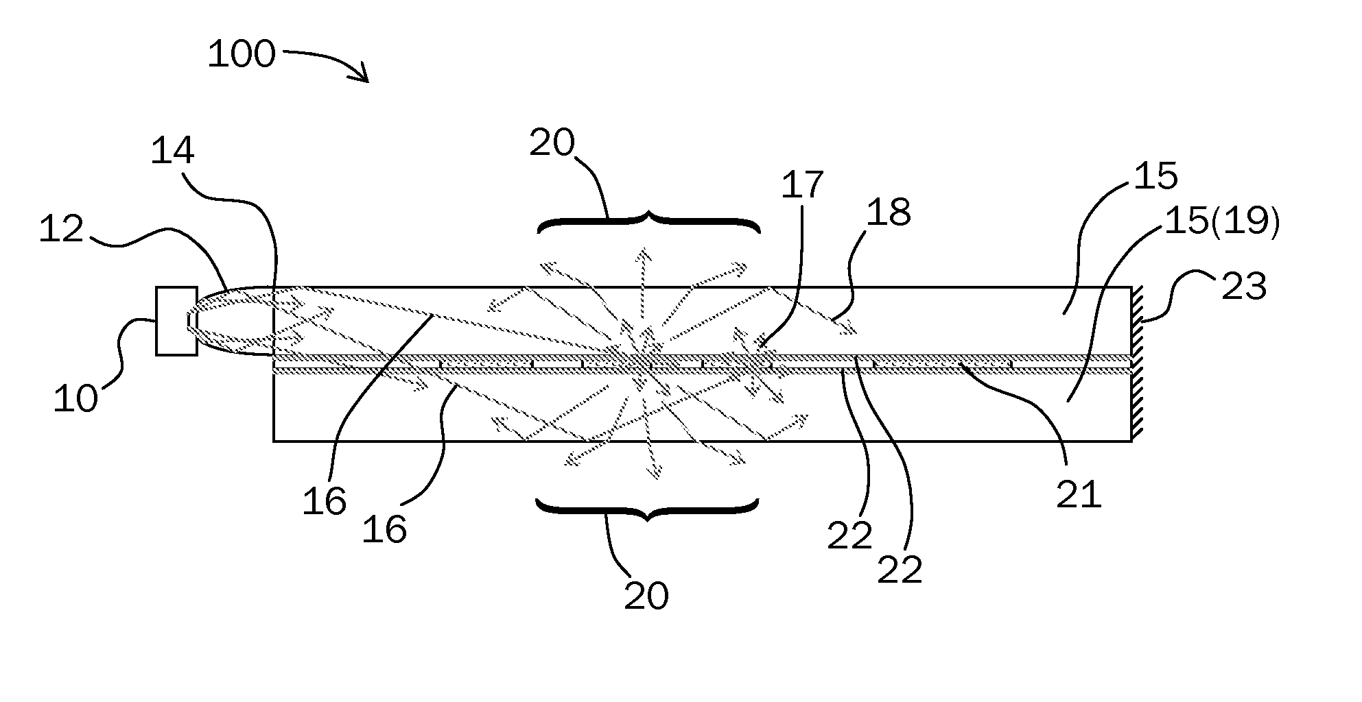
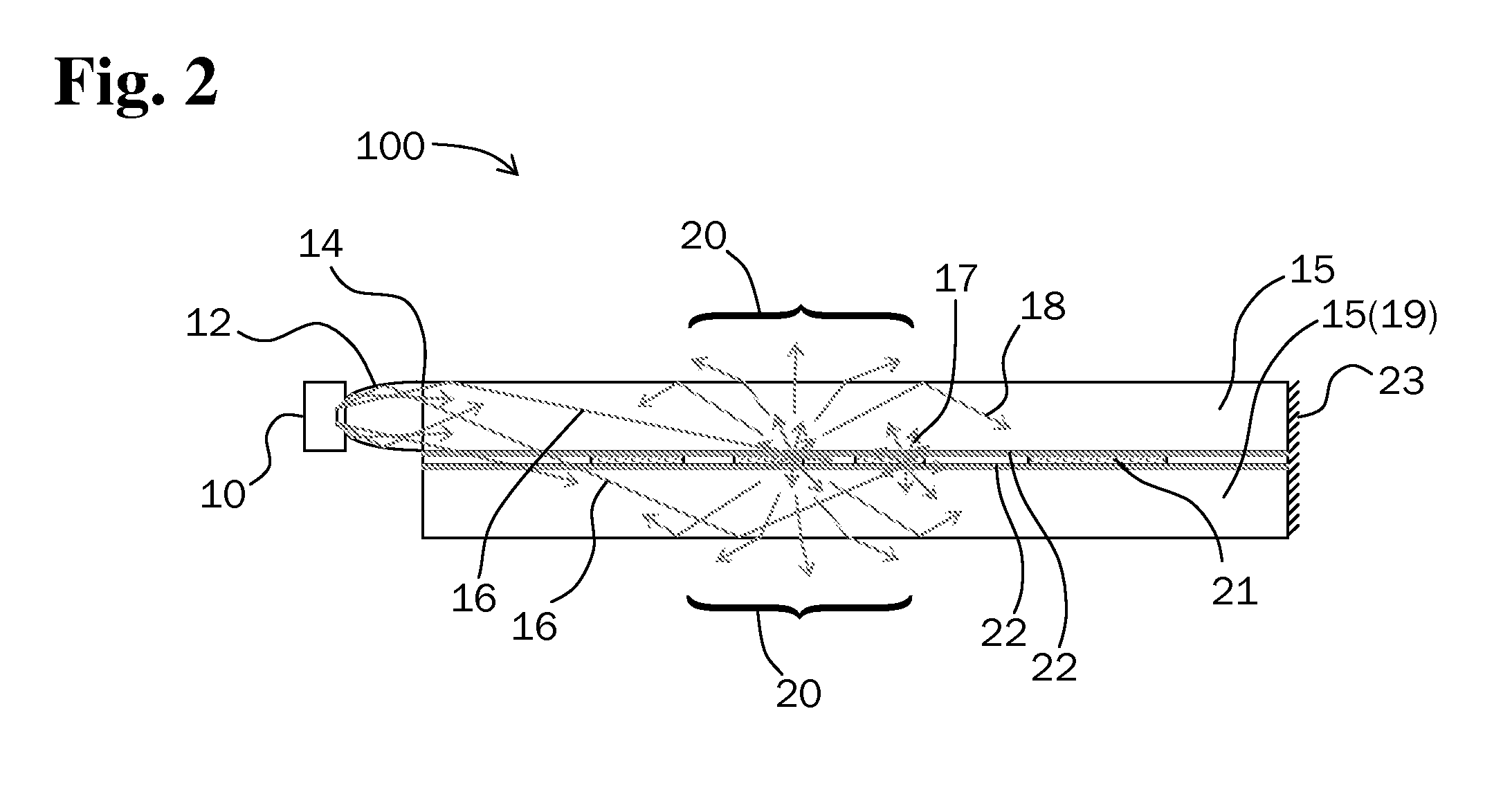
[0040]Referring to the accompanying Figs. there is shown a lightguide illuminator embedded display 100 that provides a viewable display that can be seen from both sides of the display. It should be noted that the lightguide illuminator embedded display 100 can function for a continuum of wavelengths of visible light as well as ultraviolet, infrared, far-infrared, and other radiation wavelength ranges, depending on the choice of material used to form the collection optics 12, coupling optics 14, lightguide illuminator 15, ...


PUM

PropertyMeasurementUnit
thicknessaaaaaaaaaa
thicknessaaaaaaaaaa
transparentaaaaaaaaaa

Abstract

A polymer-dispersed liquid crystal based display is embedded inside a lightguide illuminator sheet which provides illumination of the display without the need for a backlight or frontlight. Light from one or more light sources is coupled into the lightguide sheet and is guided within a range of high angles of incidence within the sheet by total internal reflection. The guided light illuminating portions of the display which are in diffusing state is scattered such that some of the light is allowed to escape total internal reflection, providing visibility of the display. Guided light illuminating portions of the display which are in non-diffusing state remains guided within the lightguide illuminator sheet. Combining multiple lightguide embedded displays can be used to provide a three-dimensional display. When a low refractive index cladding is applied to the surfaces of the lightguide embedded display, the display is robust in a dirty environment, and/or can be laminated to adjacent lightguide embedded displays. The use of one or more coupled light sources, such as light emitting diodes, provides color by combining one or more colored light sources or by time-sequentially driving one or more colored light sources. The lightguide illuminator embedded display may further be used as a content dependent active backlight for an LCD display panel to provide improved dynamic contrast.

Description

[0001]This utility patent application is based on the U.S. provisional patent application (Ser. No. 61 / 279,107) filed on Oct. 16, 2009.BACKGROUND OF THE INVENTION[0002]1. Field of the Invention[0003]The present invention relates to a slim form factor display embedded inside an optical lightguide illuminator sheet, or a display combined with an optical lightguide illuminator sheet in such a way that the display serves as a display embedded inside an optical lightguide illuminator sheet, and a system that uses the lightguide embedded display for a display device.[0004]2. Description of the Related Art[0005]While a variety of solid-state display devices have been developed in the past, Liquid Crystal Displays (LCDs) are attractive due to low cost, reliability, low power and voltage requirements, longevity, and availability. As a display source however, LCDs require a separate illumination source. Typical fluorescent backlights, such as cold-cathode fluorescent (CCFL), have high voltage...

Claims


Application Information

Patent Timeline
Patent Type & Authority Applications(United States)
IPC IPC(8): G02F1/13357
CPCG02F1/1334G02F1/133615G02F2001/133622G02F1/195G02F2001/133616G02F1/13476G02F1/133622G02F1/133616
Inventor POWELL, KARLTON DAVIDNESTOROVIC, NENAD
Owner POWELL KARLTON DAVID
Why Eureka
Try Eureka