
Antireflective film and production method thereof

a technology of anti-reflective film and production method, which is applied in the field of anti-reflective film, can solve the problems of insufficient anti-reflective film not only in anti-reflective property, and achieve the effect of improving light transmissivity and anti-reflective property

Inactive Publication Date: 2011-06-30
DNP FINE CHEMICALS CO LTD
View PDF3 Cites 11 Cited by
  • Summary
  • Abstract
  • Description
  • Claims
  • Application Information

AI Technical Summary

Benefits of technology

[0029]According to the present invention, it is enabled to provide an antireflective film improved in antireflective property for light, light transmittivity, and the like. Specifically, it is enabled to provide an antireflective film which is particularly improved in light transmissivity, as an antireflective film, transmissivity improving film, surface protective film, or the like, such as a surface layer of an FPD or the like.

Problems solved by technology

However, these antireflective films have been insufficient not only in antireflective property for light, and particularly but also in light transmitting property, and thus have been demanded to be further improved.

Method used


Image

  • Antireflective film and production method thereof
  • Antireflective film and production method thereof
  • Antireflective film and production method thereof

Examples


example 1

[0107]A rolled aluminum plate of 99.85% (2 mm thickness) as an aluminum material was polished for 10 minutes by a single-sided flat buff polishing machine (manufactured by Speedfam Co., Ltd.) and by adopting an alumina-based abrasive (produced by FUJIMI INCORPORATED), to obtain a mirror surface. The polished surface was scrub cleaned, and a non-corrosive degreasing treatment was conducted thereafter.

[0108]Further, the following condition of anodic oxidation was combined with the following etching (pore diameter enlarging) treatment condition for the formed anodic oxide coating, to produce a mold having taper-shaped pores.

[0109]Used solution: 0.05M oxalic acid[0110]Voltage: DC voltage of 80V[0111]Temperature: 5° C.[0112]Time: 50 seconds

[0113]Used solution: 2 wt % phosphoric acid[0114]Temperature: 50° C.[0115]Time: 5 minutes

[0116]The anodic oxidation and the etching (pore diameter enlarging) were alternatingly repeated 5 times, to obtain an anodic oxide coating surface having taper-sh...

example 2

[0124]Conducted was the same procedure as Example 1 to obtain an antireflective film, except that polishing was conducted by a board buff with an abrasive containing colloidal silica (produced by FUJIMI INCORPORATED) as a main component, instead of polishing by an alumina-based abrasive in Example 1.

example 3

[0125]Conducted was the same procedure as Example 1 to obtain an antireflective film, except that polishing was conducted by a bias buff (manufactured by Koyo-Sha Co., Ltd.) with a silicic anhydride-based abrasive oil (produced by ICHIGUCHI Corporation), instead of polishing by an alumina-based abrasive in Example 1.


PUM

PropertyMeasurementUnit
heightaaaaaaaaaa
heightaaaaaaaaaa
hazeaaaaaaaaaa

Abstract

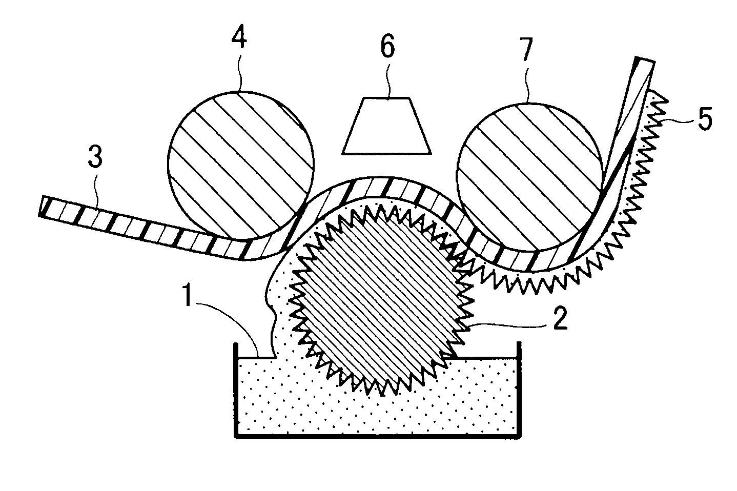
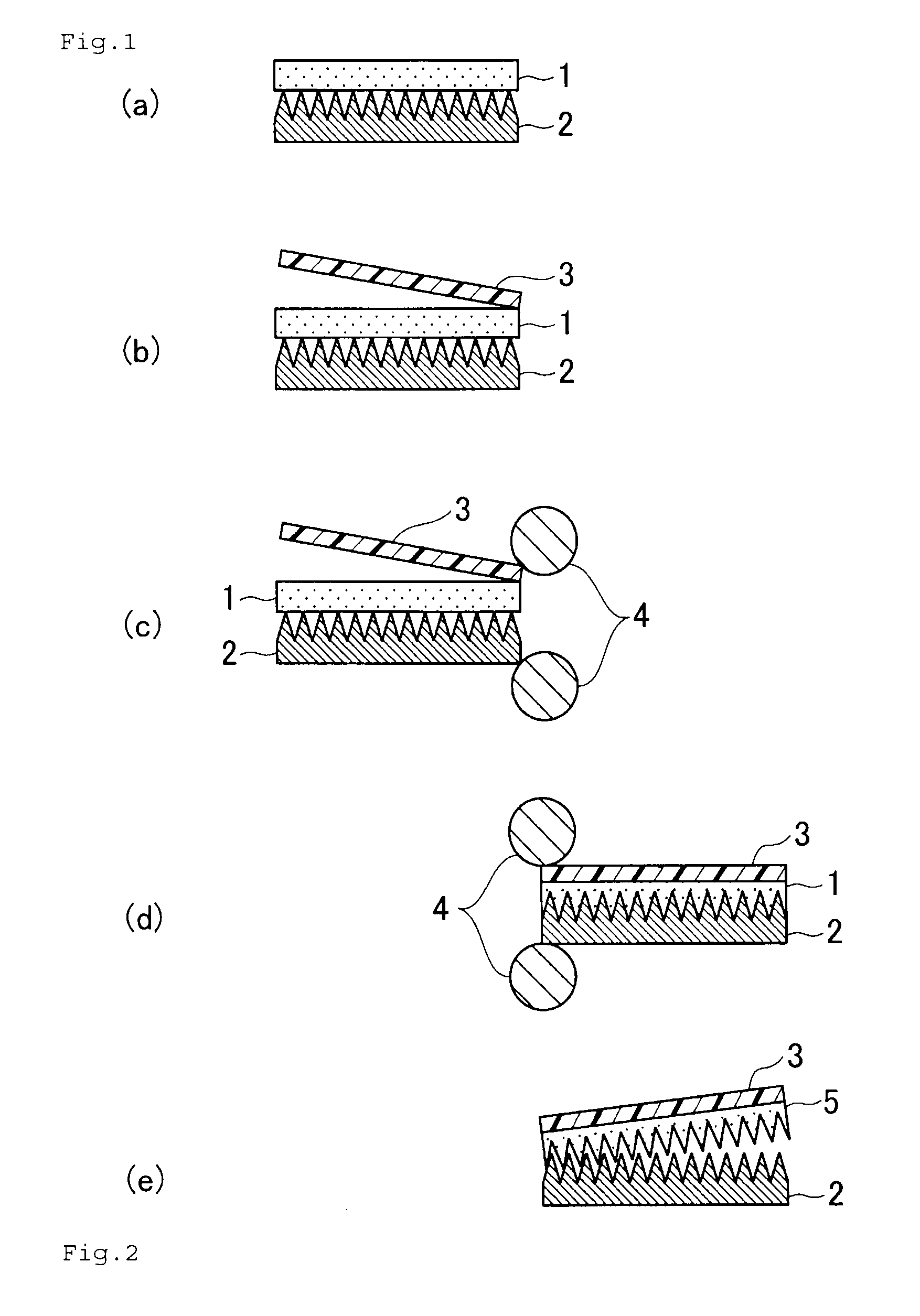
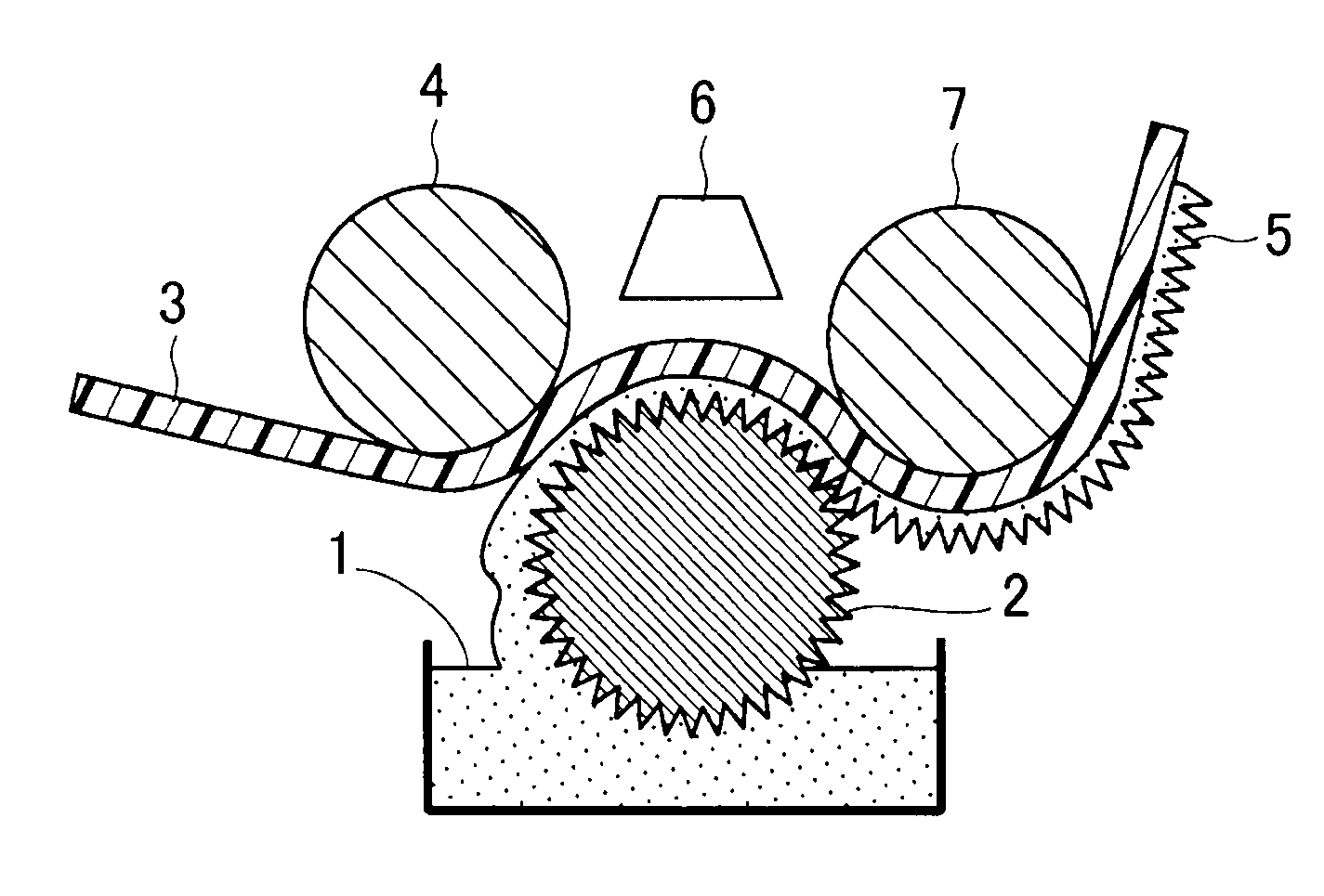
It is aimed at finding out a surface pattern and physical properties required for an antireflective film having an excellent antireflective property for light, a light transmissivity, and the like, and at providing an antireflective film having such a specific surface pattern and physical properties, and a production method of the antireflective film; and provided for this object, is an antireflective film, obtained by: processing a surface of an aluminum material, by mechanical polishing, chemical polishing and / or electrolytic polishing; subsequently producing a pattern of mold having taper-shaped pores on the surface of the aluminum material, by combining a formation of an anodic oxide coating based on anodic oxidation of the surface of the aluminum material, with etching of the anodic oxide coating; and transferring the pattern of mold onto an antireflective film-forming material; wherein the antireflective film has, on a surface thereof, convexities having an average height between 100 nm inclusive and 1,000 nm inclusive, or concavities having an average depth between 100 nm inclusive and 1,000 nm inclusive, and the convexities or concavities are present at an average period between 50 nm inclusive and 400 nm inclusive, at least in a certain single direction; and wherein the antireflective film has a haze of 15% or less.

Description

TECHNICAL FIELD[0001]The present invention relates to an antireflective film having a specific surface pattern and specific physical properties, particularly to an antireflective film for preventing reflection of light to thereby improve light transmission therethrough, and more particularly to an antireflective film for providing a display or the like with an excellent visibility, and to a production method thereof.BACKGROUND ART[0002]It is indispensable for a flat panel display (hereinafter abbreviated to “FPD”) such as a liquid crystal display (LCD), and plasma display (PDP), to be provided with an antireflective film for ensuring a visibility thereof. As such antireflective films, there have been used (1) one obtained by a typically called “dry method”, i.e., one obtained by producing a multilayered dieletric film by a vapor phase process to thereby realize a lower reflectivity by virtue of an optical interference effect; (2) one obtained by a typically called “wet method”, i.e....

Claims


Application Information

Patent Timeline
Patent Type & Authority Applications(United States)
IPC IPC(8): G02B1/11B24B1/00C25D5/34B29C33/38B29C43/00B29C59/02B29K33/04B29L11/00G02B1/118
CPCB29C33/38B29C35/0888G02B1/118B29C2035/0827B29C59/046G02B1/111G02B1/12
Inventor SATO, KAZUYAMATSUMOTO, TSUKASAWATANABE, YUTAKAROKUHARA, JUN
Owner DNP FINE CHEMICALS CO LTD
Learn More