Offshore energy carrier production plant

a technology of energy carrier and production plant, which is applied in the direction of special purpose vessels, vessel construction, greenhouse gas reduction, etc., can solve the problems of increasing cost and risk, increasing supply, and increasing complexity, so as to reduce the reliance on fossil fuels as an energy source, increase the use of carbon free nuclear energy, and reduce the effect of production cost and capital cos

Inactive Publication Date: 2011-06-30
MORGAN DAVID B
View PDF13 Cites 11 Cited by
  • Summary
  • Abstract
  • Description
  • Claims
  • Application Information

AI Technical Summary

Benefits of technology

It is therefore a primary object of this invention to produce hydrogen and hydrocarbons from surrounding water and varying sources of carbon in an offshore sustainable, scalable, and reliable manner which will significantly decrease reliance on fossil fuels as an energy source.
It is another object of this invention to provide an environment in which a mass producible nuclear reactor can be utilized to lower production costs as well as capital costs and dramatically increase the use of carbon free nuclear energy.
It is still another object of this invention to provide a design which can be produced in mass quantities to provide both operational cost efficiency as well as scalability required to meet global energy demands.

Problems solved by technology

The need for a long-term replacement of fossil fuels, which are naturally existing energy carriers, is an ever increasing need due to the limited supply of fossil fuels as well as the destructive releases of carbon emissions and other harmful elements, molecules, and compounds into the atmosphere that occur as the energy is released by use of fossil fuels.
Carbon sequestration in addition to other environmental mitigations is proving to be costly as well as risky since the true impact of these measures may not be known for decades.
However, conventional methods of using nuclear energy for peaceful purposes involves land investments in addition to interior water resources for process cooling both of which are needed to sustain human life and are becoming increasingly sparse in supply, especially in habitable U.S. locations.
Nuclear proliferation, accident, and terrorist concerns also exist as many nuclear power plants today are located in or near dense population areas which adds complexities to fully protecting nuclear material as well as limiting public exposure to potential incidents and hazards.
In addition, interior water resources used and consumed by most nuclear power plants adds to already overburdened interior water supply systems which are needed to sustain human life through both potable water supplies as well as agricultural irrigation water supplies.
The fundamental flaw is the limited method used to distribute the energy.
The complexity of the design is just one possible reason the plant was never built.
U.S. Pat. No. 3,962,877 is an “offshore power plant in which the steam generators of the power plant are located within the support structure carrying the components of the power plant.” It further describes, “instead of transporting the produced natural gas to the mainland, to convert it into electric power directly at the well head.” This patent again has the weakness of relying on electrical transmission to shore as well as being restricted to locations which have natural gas as an energy source and does not involve a nuclear power source.
Also, the submerged devices would be prone to maintenance access issues for major repairs.
It provided the Army with useful niche purpose electrical power generation, however, the concept failed to have broader energy implications as history shows offshore nuclear power plants have failed to provide commercial viability.
While the floating nuclear power plants have the possible advantage of mass production; the broader energy use is quite limited and constrained.
The paper also failed to address large scale use in any detail and limited observations to military and other limited purposes.

Method used


Image

  • Offshore energy carrier production plant
  • Offshore energy carrier production plant
  • Offshore energy carrier production plant

Examples


Embodiment Construction

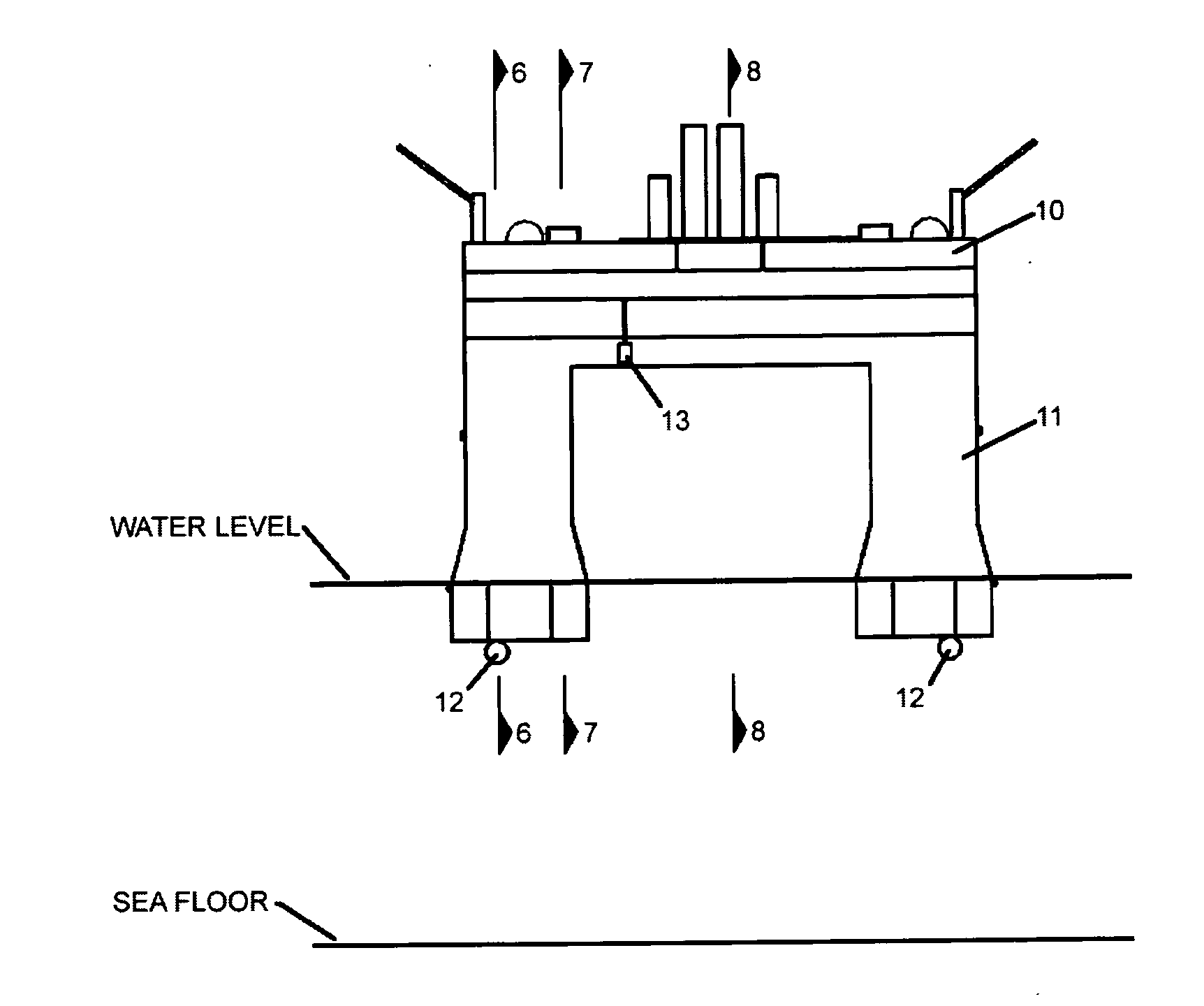
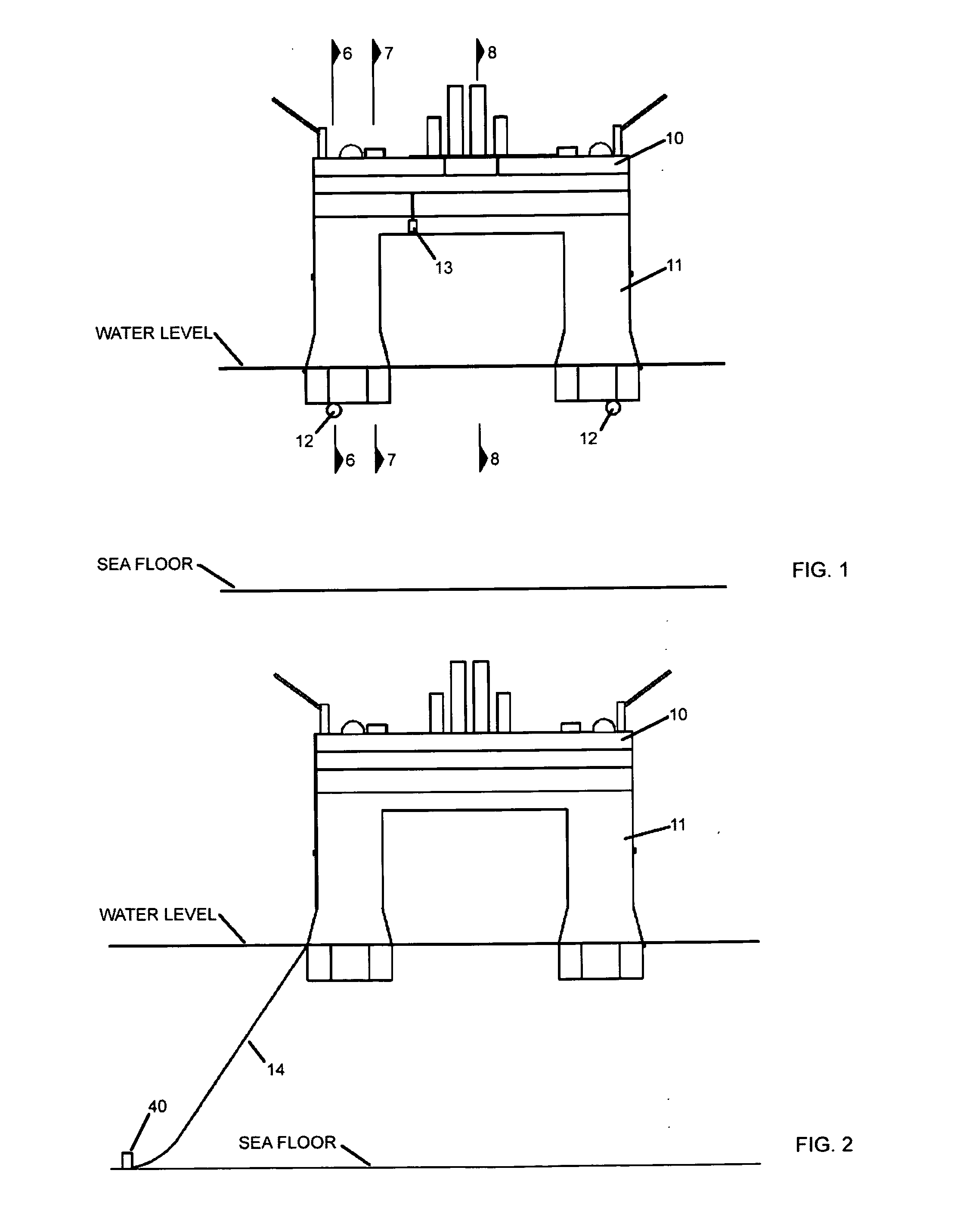
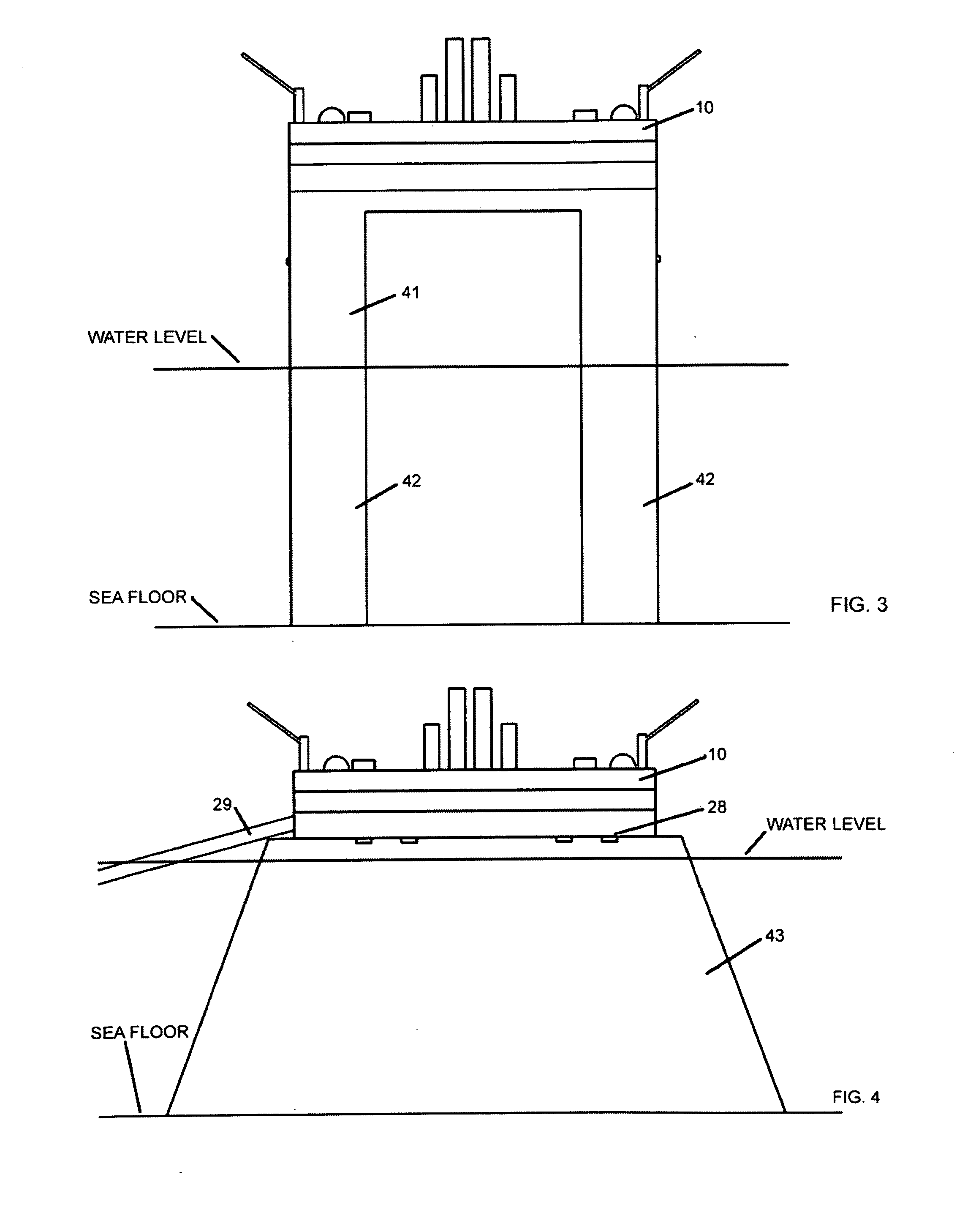
FIG. 1 shows a three-dimensional rendering of the best mode contemplated by the inventor of an offshore mobile energy carrier production plant 10, herein referred to as the plant 10 for brevity, according to the concepts of the present invention. An example of the preferred plant 10 is carried by a semi-submersible bare-deck platform 11 also known as the MOSS CS-50 deep-sea semi-submersible platform which is available from Vyborg Shipyard JSC, 2b Primorskoe Shossee 188800 Vyborg, Russia and provides the option to be equipped with a dynamic positioning system 12 for deep water use or anchorage system 13 for water depths less than 1500 m. The semi-submersible platform 11 is selected as the best mode apparatus due to the significant stability and versatility afforded by such a design, however, other mobile nautical vessels apparatus or platforms may be able to adequately function as an offshore energy carrier production plant. An alternate offshore configuration, which could be conside...


PUM


Abstract

Disclosed is an offshore fixed, moored, or mobile energy carrier production plant. The plant's energy source for the energy intensive processes of producing an energy carrier is nuclear in nature and the resulting energy carriers of the plant range from hydrogen to hydrocarbons such as methanol and jet fuel. The offshore energy carrier production plant will be able to produce energy carriers at a reduced cost, increased sustainability and scalability, increased safety, and with fewer environmental and social impacts than heretofore possible. The resulting energy carrier products can then be transported by marine vessels, pipelines, and other transportation means or any combination of transportation means thereof to be distributed to end use energy carrier consuming devices and products such as fuel cell applications in a variety of industries as well as internal combustion engines.

Description

BACKGROUND OF THE INVENTION1. Field of the InventionThe present invention relates to an offshore fixed, moored, or mobile energy carrier production plant. The plant's energy source for the energy intensive processes of producing an energy carrier is thermal nuclear in nature and the resulting energy carriers of the plant range from hydrogen to hydrocarbons such as methanol and jet fuel. The resulting energy carrier products can then be transported by marine vessels, pipelines, and other transportation means or any combination of transportation means thereof to be distributed to end use energy carrier consuming devices and products such as fuel cell applications in a variety of industries as well as internal combustion engines.2. Description of the Prior ArtThe need for a long-term replacement of fossil fuels, which are naturally existing energy carriers, is an ever increasing need due to the limited supply of fossil fuels as well as the destructive releases of carbon emissions and o...

Claims


Application Information

Patent Timeline
Patent Type & Authority Applications(United States)
IPC IPC(8): G21C1/00G21C7/32B63B35/44
CPCB63B35/44Y02E30/40G21D1/00B63B2035/4446B63B1/107Y02E30/00Y02E30/30
Inventor MORGAN, DAVID B.
Owner MORGAN DAVID B
Why Eureka
Try Eureka