
Eureka
For R&D, Eureka makes reading and utilizing patents & technical documents easy.
Eureka AIR
Designed for self-driven R&D workflows. Generate viable solutions, solve complex R&D challenges, empower your innovation with AI.

Eureka Materials
Designed for material experts only. Revolutionize your material R&D, from search, analyze, to developing new materials.

TechResearch
Generate reliable direction feasibility study reports for your R&D in just a few steps.

TechSeek
Discover and master advanced knowledge NOW. Basics, ideas, possibilities, all at once.

TechMind
As an expert in R&D Theories, TechMind can generates customized viable solutions instantly.

TechRisk
Analyze your overall solution with one click, know your potential R&D risks in advance.

TechMonitor
Get weekly tech updates, stay abreast of the latest tech innovations and key insights.
Thermal Sensor, Non-Contact Thermometer Device, and Non-Contact Temperature Measurement Method
- Summary
- Abstract
- Description
- Claims
- Application Information
AI Technical Summary
Benefits of technology
Problems solved by technology
Method used
Image

Examples
first embodiment
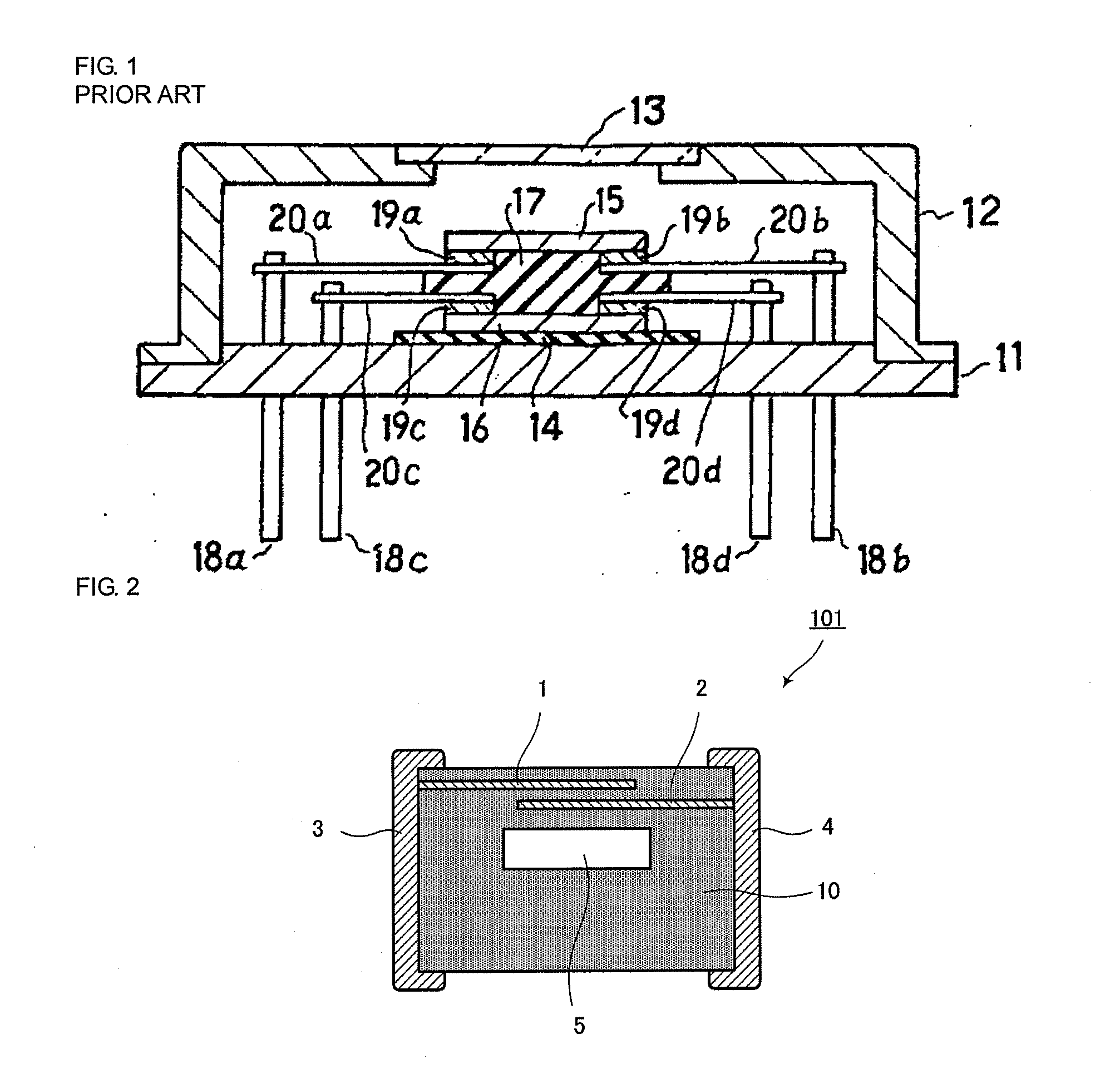
[0079]FIG. 2 is a sectional view of a thermal sensor 101 according to a first embodiment. The thermal sensor 101 includes a ceramic body 10, which is the main body of the thermal sensor and is formed of negative temperature coefficient (NTC) thermistor ceramic, heat sensing part electrodes 1 and 2, external electrodes 3 and 4, and a cavity 5.
[0080]The vicinity of the surface layer of a first main surface of the ceramic body 10 serves as the heat sensing part and is heated by the transfer of convective heat, radiant heat, or the like from the heat source. The heat sensing part electrode 1 and 2 are disposed in positions that are in the vicinity of the above-mentioned surface layer of the ceramic body 10 and where the resistance value of the thermistor of the heat sensing part is detected. Specifically, the heat sensing part electrode 1, on the one hand, expands in the form of a plane at a given depth from the surface of the ceramic body 10 to which convective heat or radiant heat fro...
second embodiment
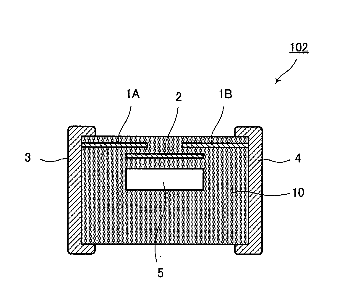
[0103]FIG. 4 is a sectional view of a thermal sensor 102 according to a second embodiment. The thermal sensor 102 includes a ceramic body 10 formed of NTC thermister ceramic, heat sensing part electrodes 1A, 1B, and 2, external electrodes 3 and 4, and a cavity 5.
[0104]The heat sensing part electrodes 1A, 1B, and 2 are disposed in positions where the resistance value of the thermistor layer interposed between the heat sensing part electrodes 1A and 1B of the heat sensing part is detected. In the detection of radiant heat (infrared radiation) from an object to be measured, the heat sensing part electrodes 1A and 1B expand in the form of planes in a layer at a given depth from the surface of the ceramic body 10 on which infrared radiation is incident, while the heat sensing part electrode 2 expands in the form of a plane in a layer at a given depth from the surface so that parts thereof are opposed to the heat sensing part electrodes 1A and 1B with a thermistor ceramic layer therebetwe...
third embodiment
[0109]FIG. 5 is a sectional view of a thermal sensor 103 according to a third embodiment. The thermal sensor 103 includes a ceramic body 10 formed of NTC thermister ceramic, heat sensing part electrodes 1 and 2, external electrodes 3 and 4, a cavity 5, and a porous part 9.
[0110]The above-mentioned porous part 9 is a periphery of the thermistor ceramic body forming the surrounding of the cavity 5 and is a part made porous when fired. Specifically, an organic substance which is to disappear during firing is previously distributed in a ceramic green sheet having an aperture where the cavity 5 is to be formed.
[0111]For example, in the structure shown in FIG. 2 in the first embodiment, the heat insulation effect is increased as the width of the cavity 5 is increased. On the other hand, in order to secure the cavity 5, the periphery supporting the surrounding of the cavity 5 must be left. For this reason, the periphery supporting the surrounding of the cavity 5 is made porous, as shown in...
PUM
 Abstract
Description
Claims
Application Information
 - R&D Engineer
- R&D Manager
- IP Professional
- Industry Leading Data Capabilities
- Powerful AI technology
- Patent DNA Extraction
Browse by: Latest US Patents, China's latest patents, Technical Efficacy Thesaurus, Application Domain, Technology Topic, Popular Technical Reports.
© 2024 PatSnap. All rights reserved.Legal|Privacy policy|Modern Slavery Act Transparency Statement|Sitemap|About US| Contact US: help@patsnap.com