

Biochar Production Method and Composition Therefrom
a biochar and production method technology, applied in the field of biochar, can solve the problems of limited utility of increasing biomass production (i.e., increasing tree growth), and a large portion of biomass decompose, and achieves the effects of enhancing soil fertilization, reducing the amount of carbon sequestration, and reducing the amount of biomass
- Summary
- Abstract
- Description
- Claims
- Application Information
AI Technical Summary
Benefits of technology
Problems solved by technology
Method used
Image

Examples
example 1
[0079]All samples were assayed in duplicate for each procedure. The water used for preparation of all solutions and rinsing of glass ware was purified with a MilliTMQ water system (Millipore Corporation, Bedford, Massachuetts) attached to a house distilled water line. All incubations of char materials with solutions were carried out at ambient temperature (21-25° C.). A rotary shaker (innova 2100 platform shaker) was used to agitate samples during incubation. Weights less than 100 g were determined with a Mettler AE163 analytical balance while weights greater than 100 g were determined with a Mettler PM 4600 Delta range top loader balance. A vacuum oven (Cole Parmer, Chicago, Ill. 60648) connected to a house vacuum line was used to dry samples. Centrifugation was carried out in an Avanti J251 Centrifuge (Beckman Instruments, Palo Alto, Calif.) using a ILA 25.5 rotor. Conductivity measurements were made with a Traceable Portable Conductivity Meter (VWR International...
example 2
Determination of CEC Values of Biochar Samples
[0082]A modified barium chloride compulsive exchange method was used to determine the CEC for the agricultural char samples and a soil control from a standard test site in West Tennessee (University of Tennessee C-site). The method used is in accordance with the method described in Skjemstad, J. O., et al., “The Measurement of Cation Exchange Capacity of Organic Matter Fractions from Soils using a Modified Compulsive Exchange Method,”communications in Soil Science and Plant Analysis, 39(5-6), 926-937 (2008)).
[0083]For barium loading, 30 mL of 0.5 M barium chloride solution was added to each tube. The char samples were mixed by vortexing, then incubated for 2-18 hours on a shaker. The chars were pelleted by centrifugation for 15 minutes at 20,000 rpm (48,384 G) and 14° C. in a Beckman High Speed centrifuge. The barium chloride equilibration was repeated a total of four times, with adjustment of the pH to 8.5 in the barium chloride solutio...
example 3
Results of CEC Analysis
[0091]To test the accuracy of the conductivity assay method for low CEC values, four 20-mL aliquots of 0.010 M MgSO4 were weighed and titrated to a conductivity corresponding to 0.0015 M MgSO4. Assuming a simulated sample size of 0.5 g, an average value of −2.750±0.2903 cmol (+) / kg was obtained.
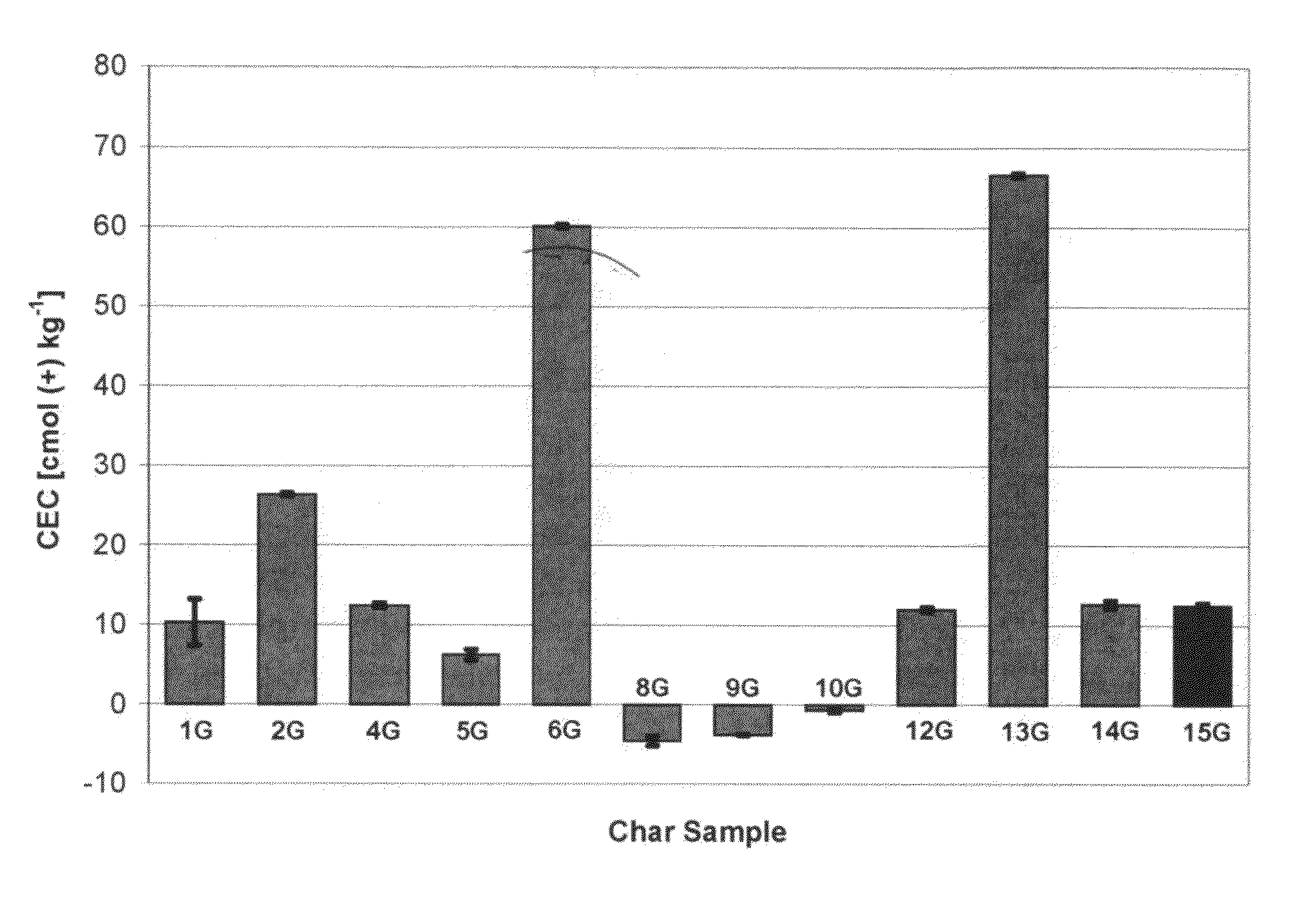
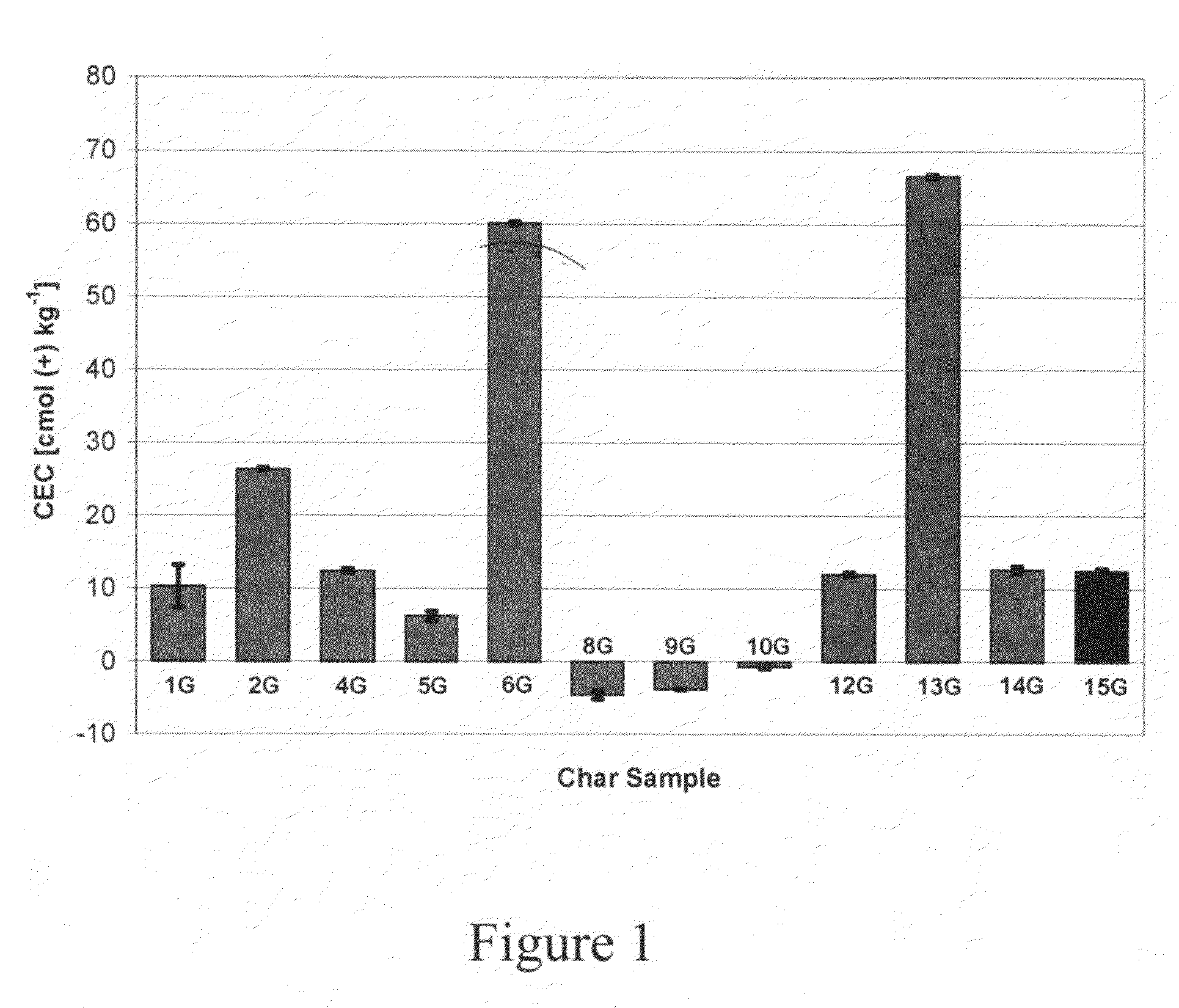
[0092]The observed cation exchange capacity of the agricultural chars varies depending on the type of pyrolytic treatment (Table 1, FIG. 1). For corn stover samples, the gasification char had lower CEC than the fast pyrolytic char.
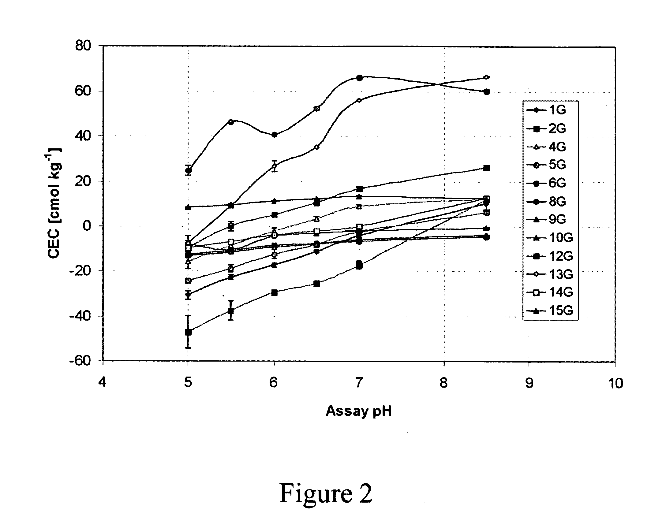
[0093]Negative CEC values were observed for pH values less than 7 (FIGS. 2, 3, 4). The pH curves for the CEC values show that the chars have ion exchange characteristics similar to those observed for humic substances. Acidification appears to result in release of bound cations, probably Ca2+, at pH values lower than 7, resulting in negative CEC values. Similar results due to the presence of Ca2+ bound to soil organic matter have been reported ...
PUM
 Abstract
Description
Claims
Application Information