Power converting apparatus

a power converter and power technology, applied in the direction of process and machine control, battery/fuel cell control arrangement, instruments, etc., can solve the problems of increasing frequency, large switching loss, and controlling charging power regardless, so as to avoid system damage, increase the capacity, and save power equipment.

Inactive Publication Date: 2011-07-21
MERSTECH
View PDF9 Cites 58 Cited by
  • Summary
  • Abstract
  • Description
  • Claims
  • Application Information

AI Technical Summary

Benefits of technology

[0014]Regarding charging devices with a large capacity, ones which are highly-efficient and not harmful to a system are desired. For example, when electric vehicles...

Problems solved by technology

However, all of those systems perform hard switching for power conversion, thus having a large switching loss.
Moreover, controlling of chargi...

Method used


Image

  • Power converting apparatus
  • Power converting apparatus
  • Power converting apparatus

Examples


Embodiment Construction

[0094]An explanation will be given of an embodiment of the present invention with reference to the accompanying drawings. The same structural elements, members, and processes will be denoted by the same reference numerals in the drawings, and duplicated explanation will be omitted. The embodiment of the present invention is not for limiting the scope of the present invention, but for exemplifying the present invention, and it is not necessary that all characteristics and the combination thereof explained in the embodiment are always requisite to embody the present invention.

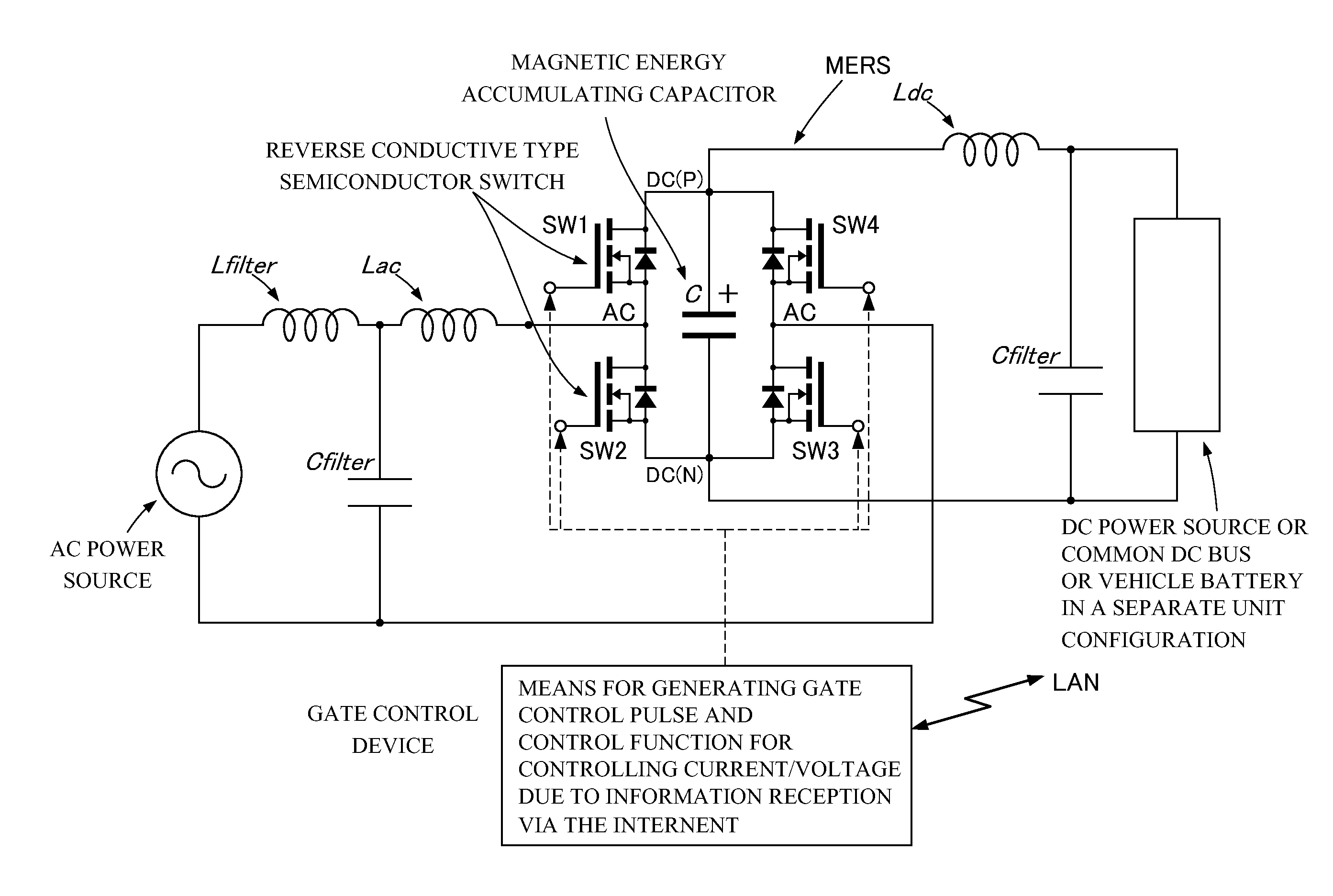
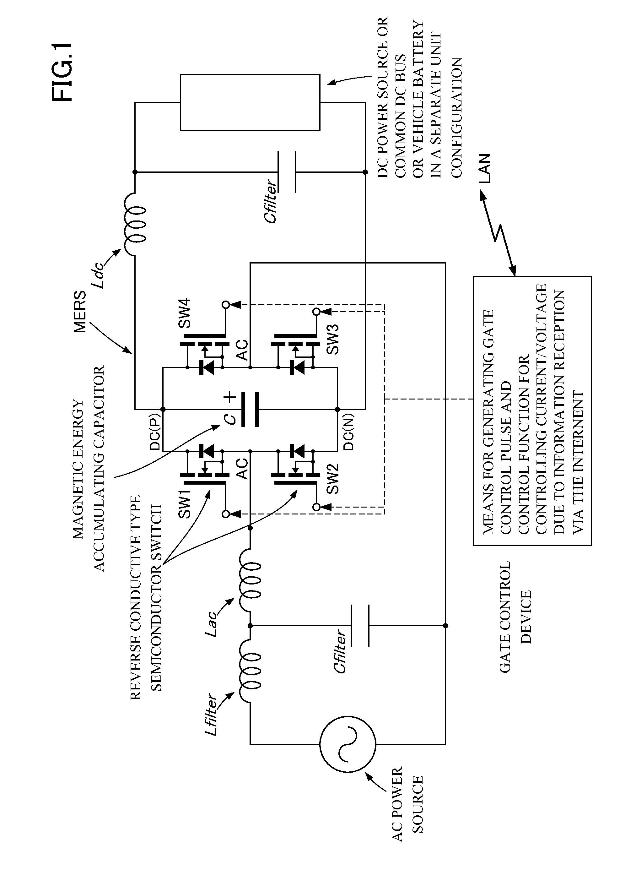
[0095]FIG. 1 is a circuit block diagram showing a schematic configuration of an electric-vehicle charging device mainly comprising a power converter using Magnetic Energy Recovery Switch (MERS) according to the embodiment of the present invention. The power converter of the present invention mainly comprises an MERS (Magnetic Energy Recovery Switch) disclosed in foregoing patent literature 5.

[0096]The Magnetic En...


PUM


Abstract

A power converter stabilizes a voltage by controlling leading of an AC current and performs maximum charging within contracted power reception amount when connected to a weak power system. The power converter comprises Magnetic Energy Recovery Switch comprising a bridge circuit including at least two reverse conductive type semiconductor switches and a magnetic energy accumulating capacitor with a small capacity connected between DC terminals of the bridge circuit. The power converter uses the Magnetic Energy Recovery Switch to perform power conversion from AC to DC or vise versa. Plurality of secondary battery charging devices each comprising the power converter have a DC part connected to a common DC bus bar, so that power is accommodated among the secondary battery charging devices.

Description

Technical Field[0001]The present invention relates to a power converter which can perform reverse conversion from AC power or DC power to DC power and more particularly, a power converter which is used for a charging / discharging device that charges / discharges a secondary battery (battery) of electric vehicles.Background Art[0002]Conventionally, simple transformer which steps down a single-phase 100 V in Japan and a diode rectifier are used in order to charge a secondary battery like a vehicular battery. For large-capacity charging, various schemes for power conversion from AC power to DC power are made in practical use. High power factor and high efficiency are desired for such power conversion schemes, and reduction of the number of component parts and simplification of controlling are also desired.[0003]Charging can be performed by a PFC circuit which is the latest power conversion technology with a PWM converter and a flyback circuit using semiconductor switches that can be switc...

Claims


Application Information

Patent Timeline
IPC IPC(8): H02M7/5387
CPCB60L11/1811B60L11/185B60L2210/20H02J7/022H02M7/219Y02T90/121Y02T10/725Y02T10/92Y02T90/127Y02T90/128Y02T90/14Y02T10/7005Y02T90/16B60L3/00B60L2210/30B60L2240/547B60L2240/549B60L2240/70B60L53/22B60L53/11B60L58/25B60L53/51B60L53/52B60L53/67B60L58/10H02J7/02H02J2207/20Y02T10/70Y02T10/7072Y02T10/72Y02T90/12
Inventor KOJIMA, NAOTO
Owner MERSTECH
Why Eureka
Try Eureka