
Bipolar electrode/separator assembly, bipolar battery comprising the same and method of manufacturing the same

a separation assembly and battery technology, applied in sustainable manufacturing/processing, paper/cardboard containers, furnaces, etc., can solve the problems of low usability of high molecular solid electrolyte, low power or energy density, and low usability of series connection, so as to simplify and facilitate the related art sealing process

Inactive Publication Date: 2011-08-04
LG CHEM LTD
View PDF10 Cites 27 Cited by
  • Summary
  • Abstract
  • Description
  • Claims
  • Application Information

AI Technical Summary

Benefits of technology

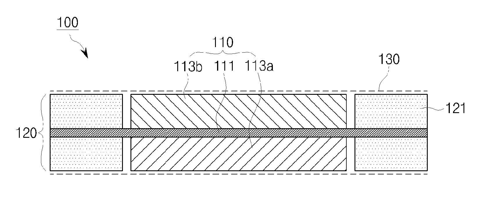
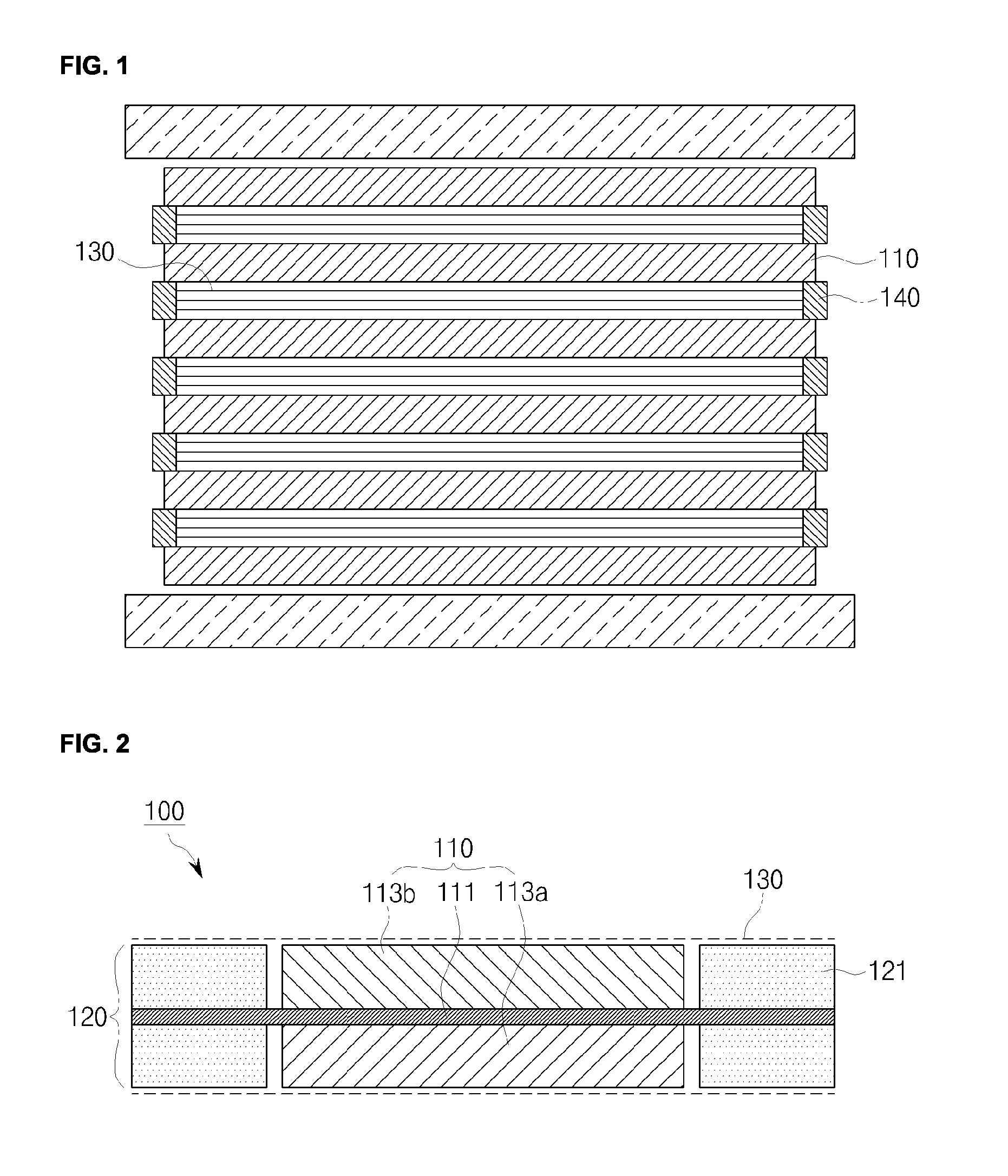
[0015]An aspect of the present invention provides a collector and a separator thermally and directly bonded together by using adhesive films applied to electrode-uncoated surfaces of the collector in a bipolar electrode, in order to simplify and facilitate the related art sealing process, which causes inconvenience in the process of manufacturing a bipolar battery, such as sealing both edges of a separator using a sealing resin and performing individual sealing thereupon.
[0016]Another aspect of the present invention provides a method of forming an electrolytic layer by impregnating a stack in which separators are assembled with an electrolytic liquid and subjecting the resultant stack to a cross-linking reaction, in order to avoid difficulties in injecting an electrolytic liquid and inconvenience caused in handling a separator / polymer separator impregnated with an electrolyte, and to permit the supply of a sufficient amount of electrolytic liquid to the pores of an electrode plate and prevent problems caused by the flow of the electrolyte within a bipolar batter after a curing process.
[0017]Another aspect of the present invention provides a collector acting as a separation plate in a bipolar battery using the above sealing process and an electrolyte, without separately inserting a separation plate, the collector being formed of a thin metal foil, in order to realize a high energy density. That is, an object of the present invention is to accomplish the realization of high energy density, effective and reliable sealing, ease of sealing process, and convenience in manufacturing and maintaining a battery.

Problems solved by technology

However, this series connection is effective only when the unit electrode stacks are completely electrochemically separated from each other.
However, the high molecular solid electrolyte has low usability due to its lower ion conductivity than that of a high molecular gel electrolyte, and its low power or energy density in a general operational environment.
This may complicate processes and incur high costs in practical terms.
However, such a bipolar battery has a limitation in that the electrolytic liquid within the electrolytic layer may leak out and come into contact with an electrode or an electrolyte of another individual electrode pair, causing short-circuits.
In general, such sealing portions are formed through a very complicated process of applying / injecting a polymer resin to the periphery of a separator and performing compression or applying heat thereon to thereby seal the separator.
However, due to the low mechanical strength and adhesiveness of the separator holding the sealing resin, inconvenience in handling may occur during the process of applying / injecting the sealing resin evenly to the periphery of the porous separator typically having a thickness of 30 microns or less and the process of positioning and assembling the separator, processed as above, between a negative electrode and a positive electrode of an individual stack.
Here, examples of the inconvenience in handling may include the attachment of separators overlapping in part, the wrinkling in part of a separator, the dislocation of a separator and the attachment of a separator to another material used together in the processes.
Furthermore, since the sealing resin having properties of blocking the flow of an electrolytic liquid makes the injection of the electrolyte difficult after the assembly, the separator positioned at the inside of the sealing resin needs to be impregnated with the electrolyte before the separator is integrated with an electrode surface.
This causes operational limitations associated with water absorption, similar to the case in which a high molecular electrolyte is used according to Japanese Patent Laid-Open Publication 2000-100471, and besides, brings about even more serious limitations in terms of the handling of the separator impregnated with the electrolyte.
In detail, if the separator impregnated with the electrolyte comes into contact with the surface of assembly equipment such as handling jigs, a portion of the electrolyte smears out of the separator to contaminate such surface even after the gelation and curing, thereby requiring a repetitive washing process.
In order to fill the pores of the electrode plates with only an electrolytic liquid, the separator needs to hold an excessive amount of liquid electrolyte.
However, making the porous separator hold an excessive amount of liquid electrolyte is technically very difficult to achieve.
Further, a separator holding an excessive amount of electrolyte merely serves to exacerbate the aforementioned limitations regarding the assembly process.
However, in actuality, a lithium ion battery employs a thin electrode plate and an electrolyte having relatively low ion conductivity.
For this reason, if a separation plate has a thickness greater than that of a metal foil used as a collector, significant spatial loss occurs, rapidly reducing energy storage density.

Method used


Image

  • Bipolar electrode/separator assembly, bipolar battery comprising the same and method of manufacturing the same
  • Bipolar electrode/separator assembly, bipolar battery comprising the same and method of manufacturing the same
  • Bipolar electrode/separator assembly, bipolar battery comprising the same and method of manufacturing the same

Examples


embodiment

[0068]A slurry for the positive electrode 113a, containing lithium manganese oxide (LMO) as a positive electrode active material for the positive electrode 113a, carbon black as a conducting agent, and PVDF as a binder, is applied on one side of an aluminum foil serving as the collector 111, and a slurry for the negative electrode 113b, containing a lithium titanium oxide (LTO), carbon black as a conducting agent, PVDF as a binder, is applied on the other side of the aluminum foil. Thereafter, the resultant structure is dried by hot air at a temperature of 150° C. for two minutes.

[0069]Subsequently, a modified PE polymer is applied as the adhesive film 121 to both the top and bottom surfaces of the two opposing sides of four electrode-uncoated edge surfaces of the collector 111 to be spaced apart from the edges of the electrode layers 113a and 113b at a predetermined distance.

[0070]Thereafter, a porous nonwoven fabric of a PET material as the separator 130 is stacked on both the top...


PUM

PropertyMeasurementUnit
thicknessaaaaaaaaaa
temperatureaaaaaaaaaa
thicknessaaaaaaaaaa

Abstract

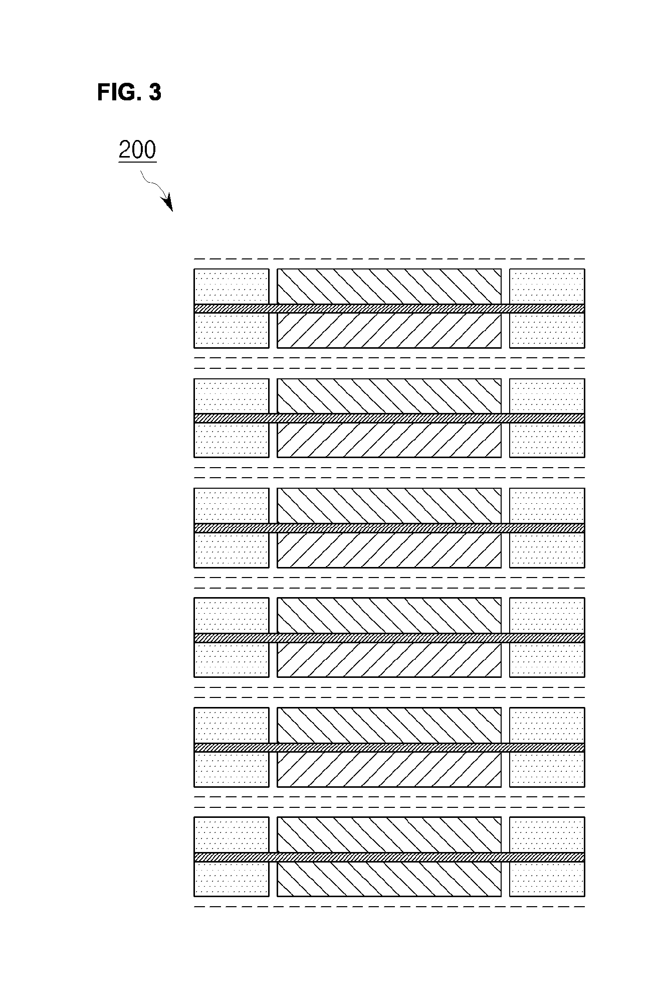
Disclosed is a bipolar electrode / separator assembly including a bipolar electrode-adhesive film assembly including a bipolar electrode holding active materials, having different polarities, on central portions of top and bottom surfaces of a collector, respectively, and adhesive films on both top and bottom surfaces of the collector with respect to at least two of four edge surfaces of the collector on which electrode layers are not coated in the bipolar electrode, and a separator stacked on one or both top and bottom surfaces of the bipolar electrode-adhesive film assembly, wherein the collector and the separator are directly bonded by the adhesive film to thereby seal the bipolar electrode. A bipolar battery including the bipolar electrode / separator assembly and methods of manufacturing the same are also disclosed. A battery having desired capacity and voltage is provided by electrically connecting such bipolar electrode / separator assemblies either in series or in parallel according to usage.

Description

[0001]This application claims the benefit of priority of Korean Patent Application No. 10-2009-0111345 filed on 18 Nov., 2009 and No. 10-2010-0114601 filed on 17 Nov., 2010, which is incorporated by reference in their entirety herein.BACKGROUND OF THE INVENTION[0002]1. Field of the Invention[0003]The present invention relates to a bipolar electrode / separator assembly, a bipolar battery including the same, and a method of manufacturing the same.[0004]The present invention is characterized in that a thin metal foil type collector is used, instead of separately inserting a separation plate, in order to realize high energy density, and adhesive films are provided on at least two of four uncoated edge surfaces of the collector on which electrode layers are absent in order to prevent the leakage of an electrolyte, and a separator is then stacked thereon, so that the collector and the separator are directly bonded by the adhesive films, thereby sealing a bipolar electrode.[0005]2. Related ...

Claims


Application Information

Patent Timeline
Patent Type & Authority Applications(United States)
IPC IPC(8): H01M8/24H01M8/04H01M8/00F27D19/00H01M4/04B32B37/02B32B37/06B32B37/12B32B37/26B32B38/10H01M10/05H01M10/38
CPCH01M10/0418Y10T156/1052Y10T156/10H01M10/052H01M10/0585H01M2300/0085Y02E60/10Y02P70/50H01M10/0565
Inventor CHUNG, GEUN CHANGYOUN, BONG KOOK
Owner LG CHEM LTD
Learn More