Pressure Sensor

a pressure sensor and pressure sensor technology, applied in the field of pressure sensors, can solve the problems of low reproducibility of the resistance value between the pressure sensitive ink layer and the electrodes due to a load, the film is sagging, and the contact between the pressure sensitive ink layer and the electrodes is difficult to control based on the load, so as to achieve the effect of reliably transmitting the pressing force, sufficient flexibility and elasticity, and ensuring the effect of sensing

Inactive Publication Date: 2011-08-18
NISSHA PRINTING COMPANY
View PDF18 Cites 12 Cited by
  • Summary
  • Abstract
  • Description
  • Claims
  • Application Information

AI Technical Summary

Benefits of technology

[0021]Because the spacer is sufficiently flexible and elastic, and also has adhesive properties,

Problems solved by technology

However, when the film deteriorates over time due to use, the upper film sags and it becomes difficult to control contact between the pressure sensitive ink layer and the electrodes based on the load.
Because of this, the reproducibility of the resistance value between the press

Method used


Image

  • Pressure Sensor
  • Pressure Sensor
  • Pressure Sensor

Examples


1st alternative embodiment

[0058]The surface of the electrodes 16 can be covered with a carbon layer 50 (FIG. 5). In FIG. 5, the electrode 16a arranged on the upper film 6 was covered with the pressure sensitive ink layer 30, and the electrode 16b arranged on the base film 31 was covered with a carbon layer 50. In this configuration, the electrode 16b can be protected by being coated with the carbon layer 50.

2nd alternative embodiment

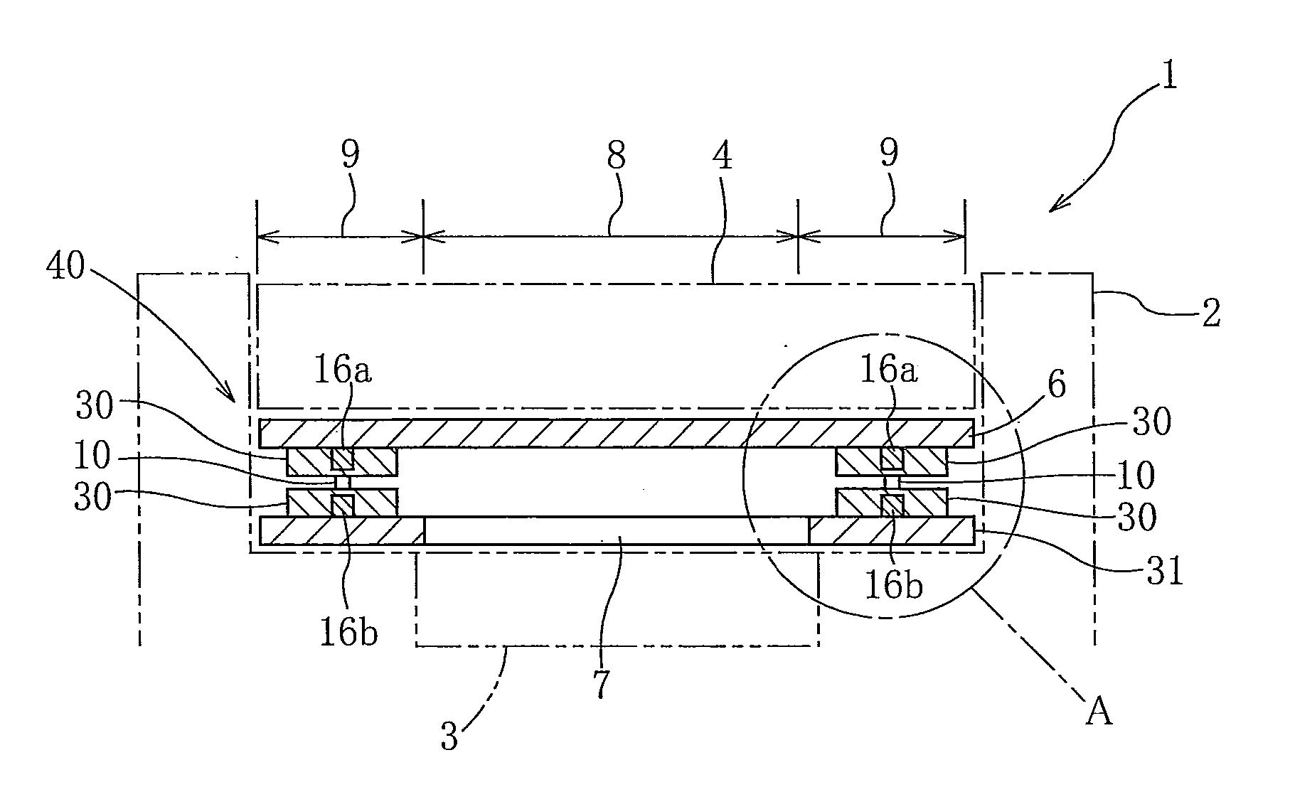
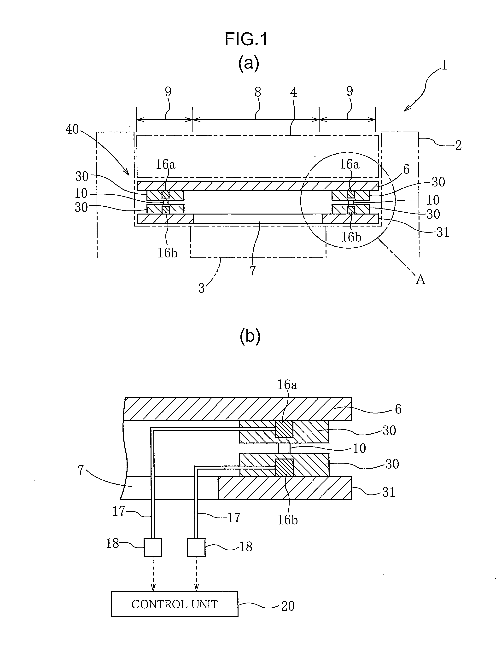
[0059]In the embodiment described above, the spacer 10 was interposed between the pair of electrodes 16a, 16b in the vertical direction. However, the present invention is not restricted to this embodiment. For example, the pair of electrodes 16a, 16b can be arranged on the base film 31 (FIG. 6). Here, the pressure sensitive ink layer 30 is arranged in certain locations so as to be able cover both electrodes 16a, 16b. Because the pair of electrodes can be arranged side by side on the base film in this configuration, the thickness of the pressure sensor can be reduced.

[0060]The pair of electrodes 16a, 16b can also be covered with a carbon layer 50 (FIG. 7).

example 1

[0061]The following is a more detailed explanation of the present invention with reference to examples and comparative examples.

[0062]

[0063]Aluminum hydroxide powder with an average particle size of 27 μm was added to pure water to prepare a slurry with a 45% powder concentration. The slurry was sprayed at a rate of 14 kg / h from the center of a two-fluid nozzle into the flames of a combustion furnace using oxygen gas with a gauge pressure of 0.2 MPa and a flow rate of approximately 12 Nm3 / h. From the burner was sprayed a gas mixture of 5 Nm3 / h LPG and 7 Nm3 / h oxygen gas for the inner flame, and from the outermost peripheral space of the burner was sprayed a gas mixture of 4 Nm3 / h LPG and 13 Nm3 / h oxygen gas for the outer flame. The alumina powder recovered from the cyclone furnace was measured using a laser diffraction scattering-type particle size distribution measuring device. The sphericity was 0.95, and the average particle size was 48 μm.

[0064]An addition reaction silicone resi...


PUM


Abstract

A pressure sensor (40) comprises a pair of electrodes (16a), (16b), a base film (31) on which at least one electrode is disposed, an upper film (6) facing the base film (31), a pressure sensitive ink layer (30) disposed so as to be able to cover the pair of electrodes (16a, 16b) and having electrical characteristics changed by applied pressing force, and a spacer (10) having adhesive properties and interposed between the base film (31) and the upper film (6).

Description

TECHNICAL FIELD[0001]The present invention relates to a pressure sensor for measuring the pressure distribution in a component perpendicular to a surface when external pressure has been applied to the surface.BACKGROUND ART[0002]An example of a configuration of a pressure sensor for distributing external pressure applied to a surface is described in Patent Literature 1. In one of these sensors, as shown in FIG. 1 of Patent Literature 1, two sheets of film are separated by a spacer to form an air layer, an upper electrode is disposed on the upper film, a lower electrode is disposed on the lower film, and a pressure sensitive ink layer is disposed between the two.[0003]When pressure is applied to the upper film, the upper electrode and the lower electrode are rendered conductive in the vertical direction in the portion sustaining the pressure, output is obtained only in the lower electrode corresponding to the intersection, and the pressure distribution is outputted. When a pressure s...

Claims


Application Information

Patent Timeline
IPC IPC(8): H01L29/84
CPCG01L1/205G01L1/20G01L5/00
Inventor OKUMURA, SHUZOOMOTE, RYOMEIKAI, YOSHIHIROTAKAI, YUICHIRO
Owner NISSHA PRINTING COMPANY
Why Eureka
Try Eureka