Honeycomb catalyst body

a catalyst body and honeycomb technology, applied in catalyst activation/preparation, metal/metal-oxide/metal-hydroxide catalysts, chemical/physical processes, etc., can solve the problems of reducing the efficiency of the engine, and reducing the pressure loss in the exhaust system. , to achieve the effect of reducing the depressor effect, and reducing the pressure loss

Active Publication Date: 2011-08-18
NGK INSULATORS LTD
View PDF9 Cites 34 Cited by
  • Summary
  • Abstract
  • Description
  • Claims
  • Application Information

AI Technical Summary

Benefits of technology

[0015]According to a honeycomb catalyst body of the present invention, since it is provided with a honeycomb substrate having porous partition walls separating and forming a plurality of cells passing through from an inflow side end face to an outflow side end face and functioning as fluid passages, and plugging portions disposed so as to plug opening portions of part of the cells in the outflow side end face of the honeycomb substrate, exhaust gas particulate matter discharged from a gasoline direct injection can efficiently be removed. In addition, since the cells opening in both the end portions (that is, through-holes passing through from th...

Problems solved by technology

However, in the case of gasoline direct injection, since PM generation is much in comparison with the case of intake port fuel injection, a countermeasure for inhibiting generated PM from being released in the atmosphere has been required.
Therefore, when a plugged honeycomb structure is further mounted in the exhaust system, pressure loss in the exhaust system increases, and a problem such as depression of engine output is considered to be caused.
However, in the plugged honeycomb structure, opening portions in an end portion of predetermined cells and opening portions in the other end portion of the remaining cells are plugged with plugging portions, and thermal capacity in both the end portions of the plugged honeycomb structure is large due t...

Method used


Image

  • Honeycomb catalyst body
  • Honeycomb catalyst body
  • Honeycomb catalyst body

Examples


example 1

[0091]Incidentally, in the first place, alumina, aluminum hydroxide, kaolin, talc, and silica were used as cordierite-forming raw materials, and to 100 parts by mass of the cordierite-forming raw materials were added 13 parts by mass of a pore former, 35 parts by mass of a dispersion medium, 6 parts by mass of an organic binder, and 0.5 parts by mass of a dispersant, and they were mixed and kneaded to prepare kneaded clay. Water was used as the dispersion medium, coke having an average particulate diameter of 1 to 10 μm was used as the pore former, hydroxypropylmethyl cellulose was used as an organic binder, and ethylene glycol was used as a dispersant.

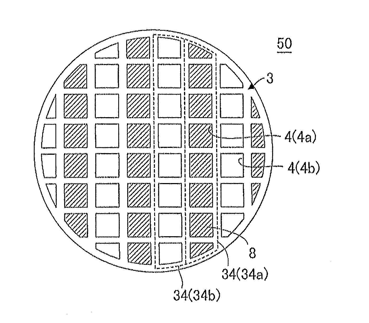
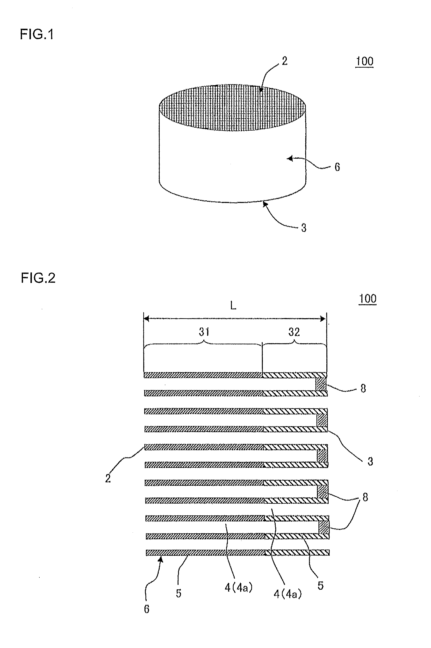
[0092]Next, kneaded clay was subjected to extrusion forming using a predetermined die to obtain a honeycomb formed article whose whole shape was a circular columnar shape (circular cylindrical shape) with a quadrangular cell shape. In addition, after the honeycomb formed article was dried with a microwave drier and further completely ...

examples 2 to 12

, Comparative Examples 1 to 8

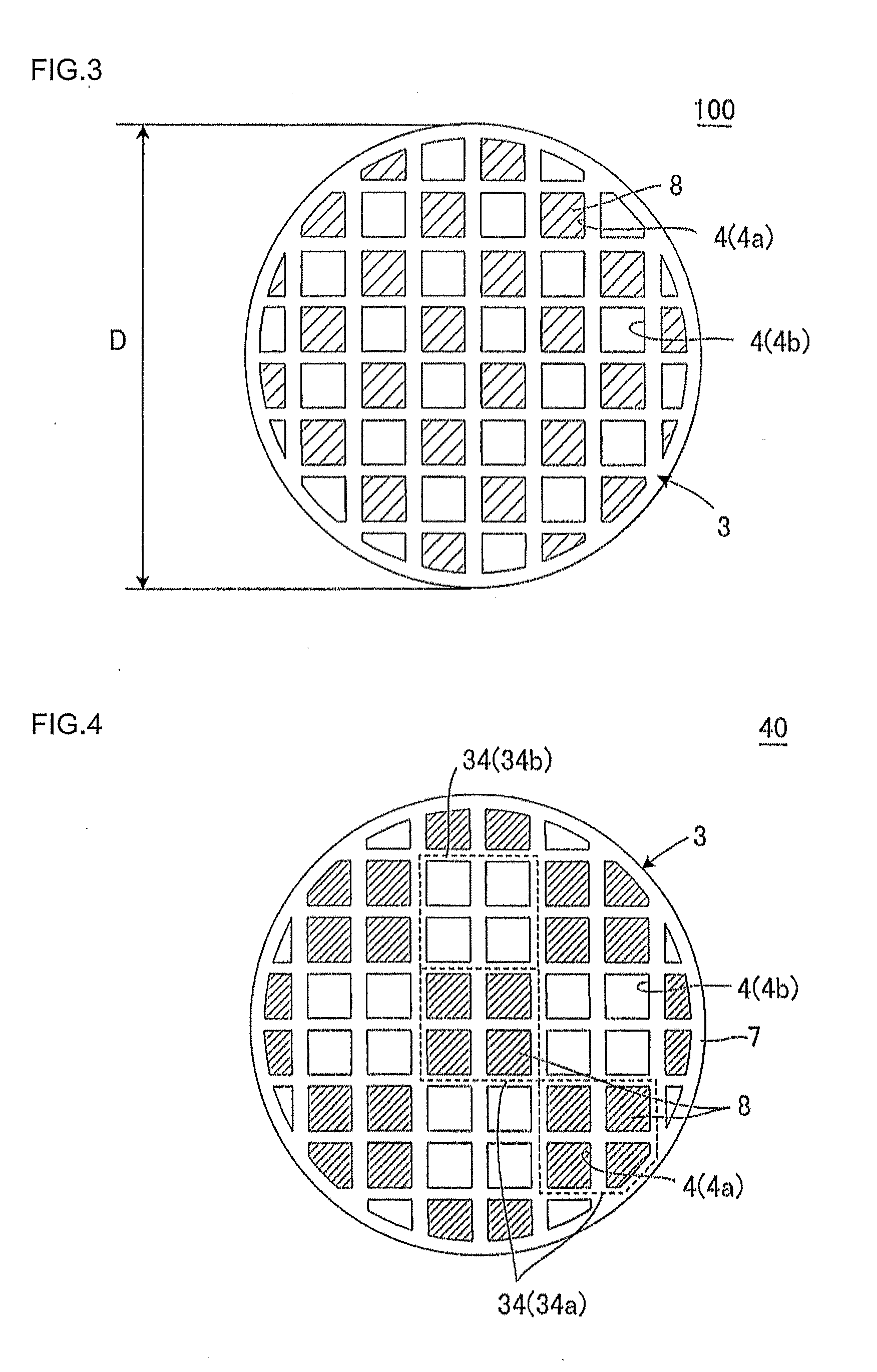
[0109]Each of the honeycomb catalyst bodies in Examples 2 to 12 and Comparative Examples 1 to 8 was manufactured in the same manner as in Example 1 except for employing the diameter, length, L / D, cell density, rib thickness, porosity, pore size, plugging portion disposition shape, length ratio, catalyst load amount in the inflow side region, noble metal amount in the inflow side region, catalyst load amount in the outflow side region, and noble metal amount in the outflow side region shown in Table 1. Then, each of the honeycomb catalyst body was put in a can to manufacture an exhaust gas purification apparatus, which was evaluated for “purification rate”, “hydrocarbon discharge amount”, “PM number emission”, “pressure loss”, and “total judgment” in the aforementioned methods in the same manner as in Example 1. The results are shown in FIG. 2.

[0110]In Table 2, “alternate every four cells” means that plugging portions are alternately disposed in adjacent ...


PUM

PropertyMeasurementUnit
Fractionaaaaaaaaaa
Lengthaaaaaaaaaa
Lengthaaaaaaaaaa

Abstract

There is provided a honeycomb catalyst body including, a honeycomb substrate, plugging portions, and a three way catalyst. All the cells are open in the inflow side end face, the honeycomb substrate has two regions of an inflow side region and an outflow side region, the inflow side region of the honeycomb substrate is a region from the inflow side end face to a position of 10 to 90% of a length in an central axial direction of the honeycomb substrate from the inflow side end face, and 100 to 400 g/L of the three way catalyst is loaded on the partition walls in the inflow side region, no catalyst is loaded on the partition walls in the outflow side region, and a ratio of the length to a diameter of the inflow side end face of the honeycomb substrate is 1.1 to 2.0.

Description

BACKGROUND OF THE INVENTION AND RELATED ART STATEMENT[0001]The present invention relates to a honeycomb catalyst body. More preferably, the present invention relates to a honeycomb catalyst body capable of efficiently removing particulate matter contained in exhaust gas discharged from a gasoline direct injection having little increase in pressure loss and purifying CO, HC, and NOx contained in exhaust gas with high efficiency right from the engine starting.[0002]Fuel consumption reduction in automobiles is demanded from the viewpoints of protection of the global environment and resource saving. Regarding a gasoline engine mainly used in a passenger vehicle, fuel direct injection is proceeding to improve gasoline mileage.[0003]Conventionally, since a gasoline engine has employed an intake port fuel injection system, soot (particulate matter: PM) generation was little and almost unquestioned. However, in the case of gasoline direct injection, since PM generation is much in comparison...

Claims


Application Information

Patent Timeline
IPC IPC(8): B01J35/04B01J35/10
CPCB01D46/2429Y02T10/22B01D46/247B01D46/2474B01D53/9454B01D2046/2433B01D2046/2437B01D2255/102B01D2255/9155B01J23/63B01J35/0006B01J35/023B01J35/04B01J37/0248C04B35/195C04B38/0009C04B2111/0081C04B2235/6567B01D46/2466C04B35/00C04B38/0054C04B38/0074C04B38/0093Y02T10/12B01D46/24492B01D46/24491B01D46/2484B01D46/2482
Inventor GOTO, CHIKAYAMASHITA, MASATAKAMIYAIRI, YUKIO
Owner NGK INSULATORS LTD
Why Eureka
Try Eureka