Blood treatment apparatus and method

a blood treatment apparatus and blood technology, applied in the direction of positive displacement liquid engine, filtration separation, separation process, etc., can solve the problems of unreliable blood flow measurement derived from the pump speed, unfavorable accurate blood flow measurement, and complicated measurement of blood flow accurately

Active Publication Date: 2011-08-18
GAMBRO LUNDIA AB
View PDF13 Cites 6 Cited by
  • Summary
  • Abstract
  • Description
  • Claims
  • Application Information

AI Technical Summary

Benefits of technology

[0004]The object of the present invention is therefore to alleviate the above problems, and provide an accurate, uncomplicated and infection / contamination safe solution for measuring blood flows where a stroke volume of a pump of membrane type is selectable.

Problems solved by technology

Hence, in designs including non-peristaltic blood pumps, it may be complicated to measure the blood flow accurately.
In fact, also when peristaltic blood pumps are used, the blood flow measure derived from the pump speed may be unreliable.
However, there is yet no such solution which renders an accurate blood flow measurement possible, and at the same time avoids the obvious infection / contamination risks associated with a multiple-use flow meter in the blood circuit.
Of course, for cost reasons, any single-use flow meters cannot be of high-quality type.

Method used


Image

  • Blood treatment apparatus and method
  • Blood treatment apparatus and method
  • Blood treatment apparatus and method

Examples


first embodiment

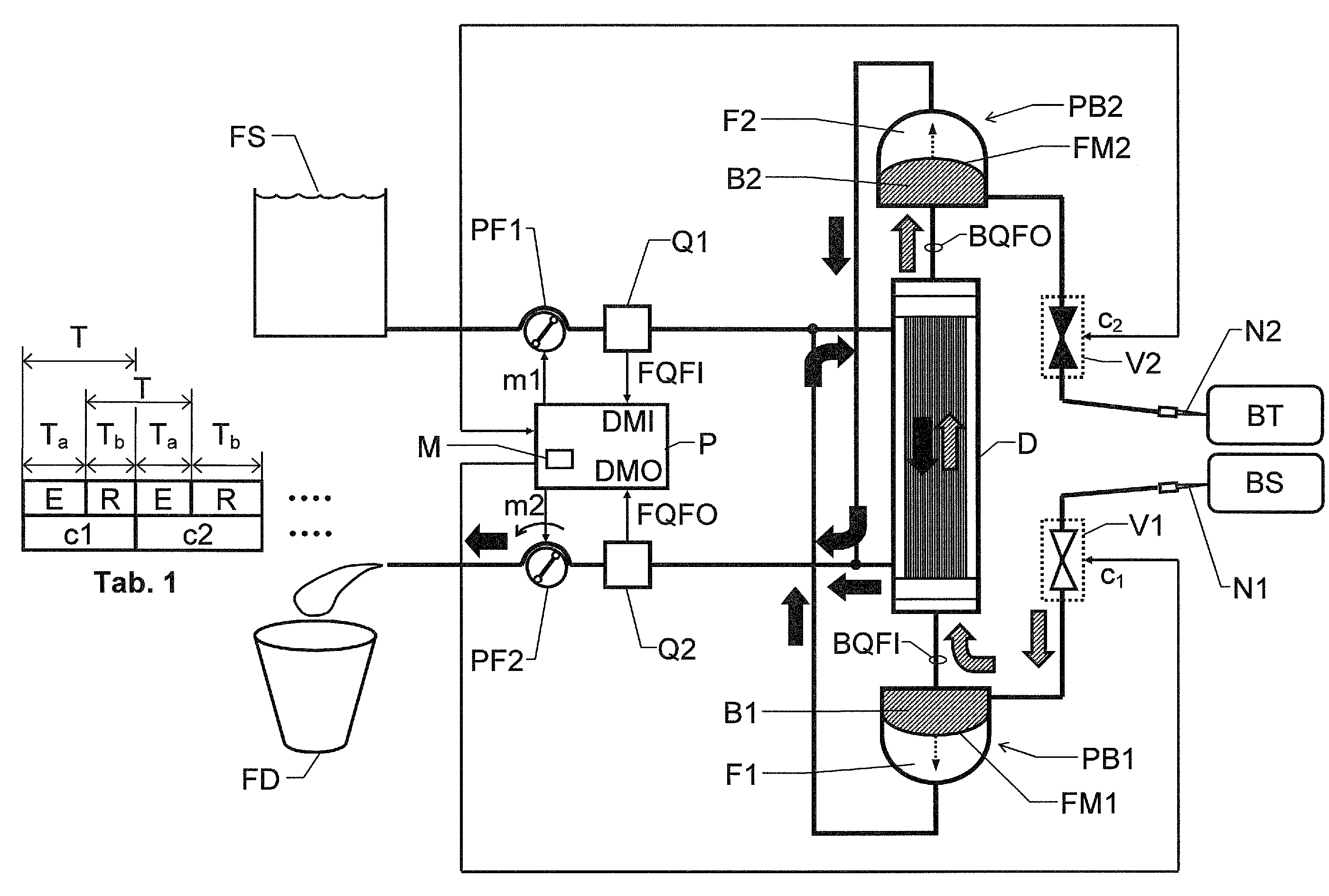
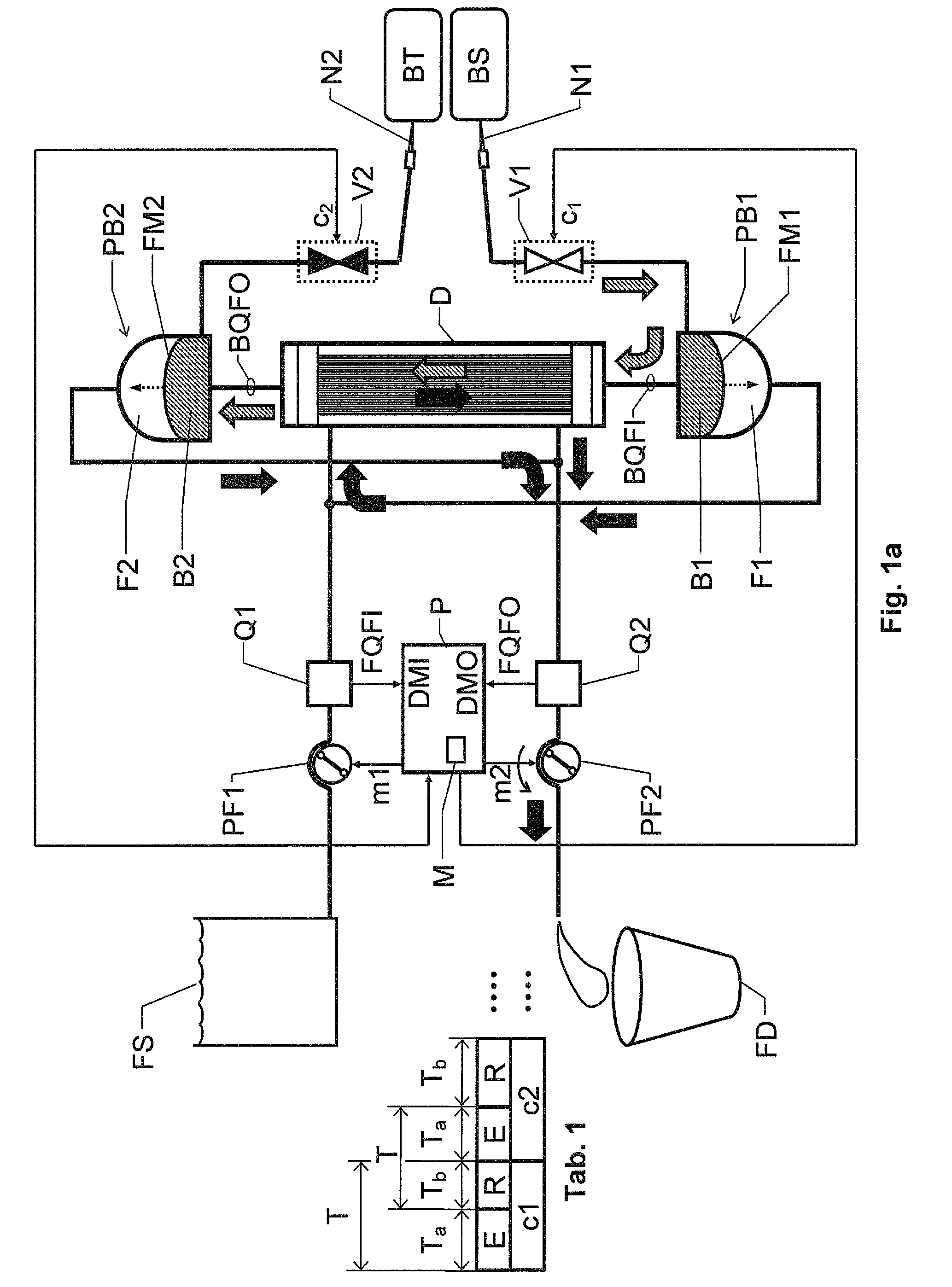
[0024]We refer initially to FIG. 1a, which shows a block diagram over a blood treatment apparatus (e.g. a dialysis apparatus) according to the invention during a first phase E of a cyclic blood treatment process.

[0025]Table 1 illustrates how the first phase E and a second phase R are related to one another. We assume that a first cycle c1 of the process includes one repetition each of the first and second phases E and R respectively. Then follows a second cycle c2, likewise including one repetition each of the first and second phases E and R, and so on.

[0026]The apparatus includes a blood treatment unit D, a pair of fluid pumps PF1 and PF2 respectively, a pair of blood pumps PB1 and PB2 respectively and flow measurement means, which in turn, include first and second flow meters Q1 and Q2 respectively and a control unit P. Moreover, the apparatus includes first and second blood valve means V1 and V2 respectively.

[0027]The blood treatment unit D is configured to receive untreated bloo...

second embodiment

[0058]FIGS. 2a and 2b show block diagrams over a blood treatment apparatus according to the invention during the first and second phases E and R respectively of the proposed cyclic treatment process. In FIGS. 2a and 2b all units and components having reference signs, which also occur in FIGS. 1a and 1b designate the same units and components as those described above with reference to FIGS. 1a and 1b.

[0059]The second embodiment differs from the first embodiment of the invention in that the blood pumps PB1 and PB2 are not cross-connected relative to the inlet and outlet for receiving fresh blood treatment fluid and discharging used blood treatment fluid respectively. Instead, first and second additional fluid pumps PF3 and PF4 respectively are included to control the blood pumps PB1 and PB2 as desired (i.e. cause the flexible members FM1 and FM2 to reach their respective end positions essentially simultaneously).

[0060]The control unit P is configured to control the first additional f...

third embodiment

[0061]FIGS. 3a and 3b show block diagrams over a blood treatment apparatus according to the invention during the first and second phases E and R respectively of the proposed cyclic treatment process. In FIGS. 3a and 3b all units and components having reference signs, which also occur in FIGS. 1a, 1b, 2a and 2b designate the same units and components as those described above with reference to FIGS. 1a, 1b, 2a and 2b.

[0062]The third embodiment differs from the first and second embodiments of the invention primarily in that the blood pumps PB1 and PB2 are controlled via a working fluid, which is separated from the blood treatment fluid. To accomplish this, in the design shown in FIGS. 3a and 3b the second accumulation container F1 of the first blood pump PB1 is connected to a first workingfluid container W1, and the second accumulation container F2 of the second blood pump PB2 is connected to a second workingfluid container W2. A respective additional fluid pump PF3 and PF4 is arrange...


PUM

PropertyMeasurementUnit
volumeaaaaaaaaaa
massaaaaaaaaaa
timeaaaaaaaaaa

Abstract

A blood treatment apparatus, including a blood treatment unit configured to receive untreated blood and fresh blood treatment fluid, and emit treated blood and used blood treatment fluid, a pair of fluid pumps configured to pass blood treatment fluid through the blood treatment unit, a pair of blood pumps configured to extract untreated blood from a blood source, pass extracted blood through the blood treatment unit and deliver treated blood to a target vessel, each blood pump including a pump chamber and a flexible member separating the pumping chamber into a first blood accumulating container and a second working fluid accumulating container where the flexible member is configured to vary a volume relationship between the first and the second accumulation containers. A control unit and a measuring device are configured to emit a feedback signal indicative of the amount of working fluid received into, or discharged from at least one of the second accumulation containers whereby the pumped mass or volume of working fluid is determined by the control unit at an arbitrary position of the flexible member.

Description

THE BACKGROUND OF THE INVENTION AND PRIOR ART[0001]The present invention relates generally to extracorporeal blood treatment. More particularly the invention relates to a blood treatment apparatus according to the preamble of claim 1 and a method according to the preamble of claim 8.[0002]A conventional blood treatment apparatus, for instance a hemodialysis system or a hemodiafiltration system, contains a dialysis fluid circuit and a blood circuit. Each circuit is normally associated with at least one pump for transporting the fluid in question. Traditionally, peristaltic pumps have been used, and here the rotational speed of the pump can serve as a basis for determining the flow through the pump, e.g. in the blood circuit. For reasons of patient security and cost efficiency it is further advantageous to avoid including dedicated flow meters in the blood circuit. Hence, in designs including non-peristaltic blood pumps, it may be complicated to measure the blood flow accurately. In f...

Claims


Application Information

Patent Timeline
Patent Type & Authority Applications(United States)
IPC IPC(8): A61M1/16B01D33/70
CPCA61M1/16A61M1/1601A61M2205/50
Inventor HOLMER, MATTIASJONSSON, LENNARTWALLENBORG, ANDERSHANSSON, PER
Owner GAMBRO LUNDIA AB
Why Eureka
Try Eureka