[0006]A sealing /
corrosion barrier
system in accordance with the invention employs a purposefully asymmetric reusable sealing element as part of an interior annular two-piece geometry employing materials of different properties in a fashion which enables long term use and repeated make-up.
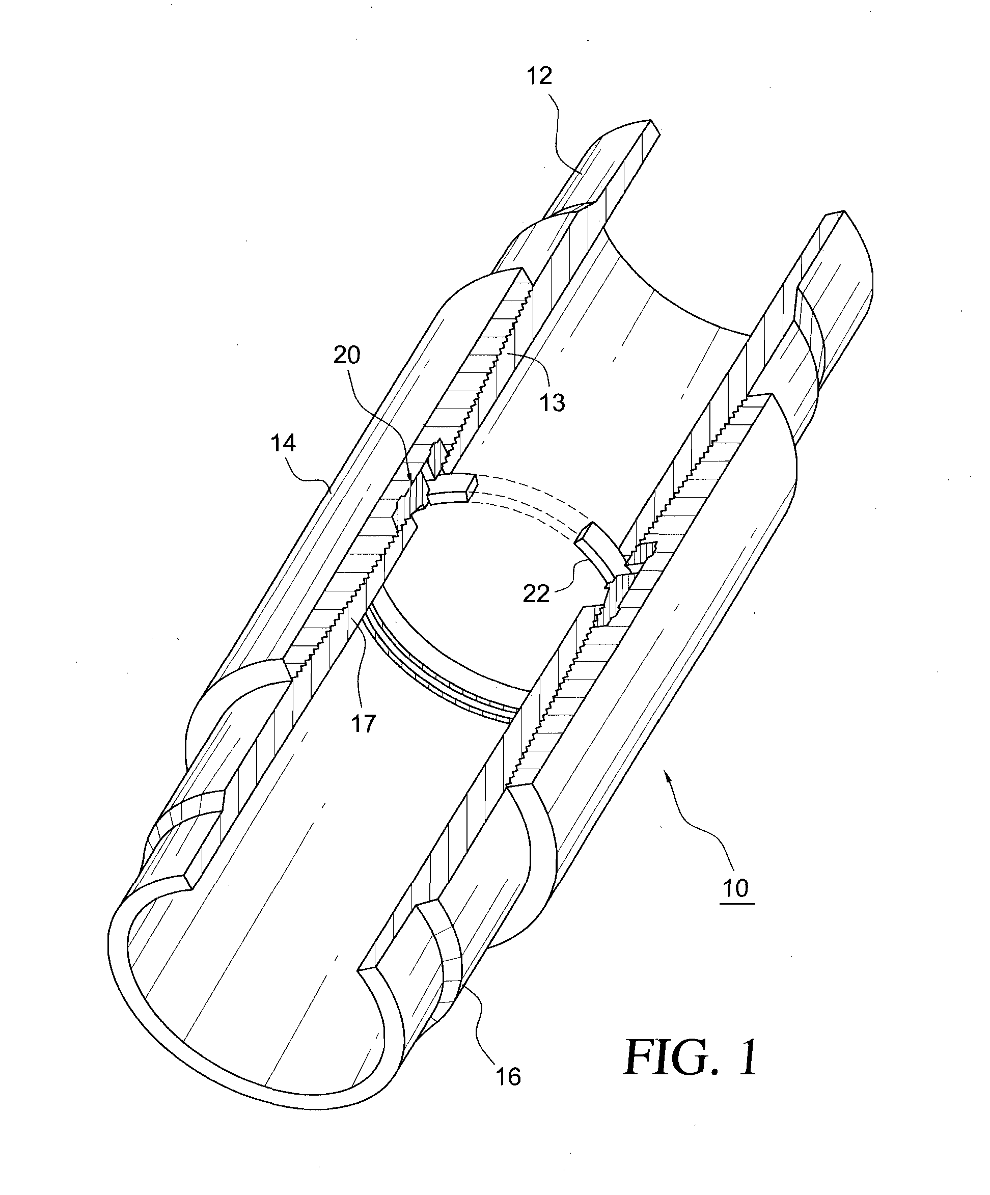
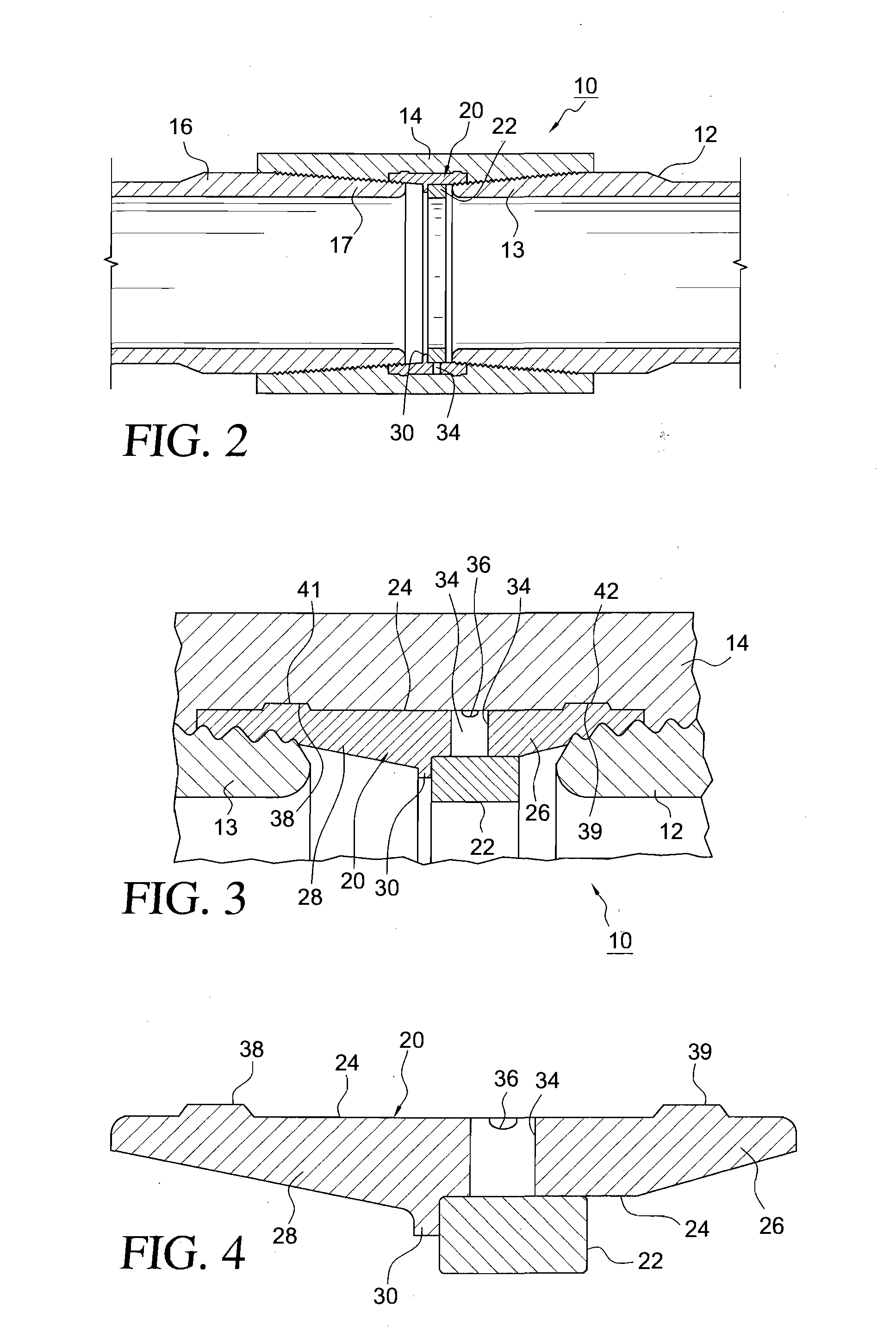
[0008]The “Teflon” body element is tapered longitudinally from its
central region in opposite direction to minimum thickness at its longitudinal ends. Again, however, these wings or tapers are asymmetric in that the length of taper on the mill end side is significantly less than the length of taper on the field end side. Within the “Teflon” body, in engagement with, and about, the constant inner
diameter portion of the body, and further in
abutment with the
retainer shoulder, is a reinforcing ring of high tensile and
corrosion resistant properties. In this example the reinforcing ring is of
polyether ether ketone (“Peek”) but it can also be made of suitable
metallic materials. The reinforcing ring has an outer circumference flush with the inner surface of the central seal / corrosion barrier body and an inner circumference substantially flush with the inner surfaces of the pin ends of inserted
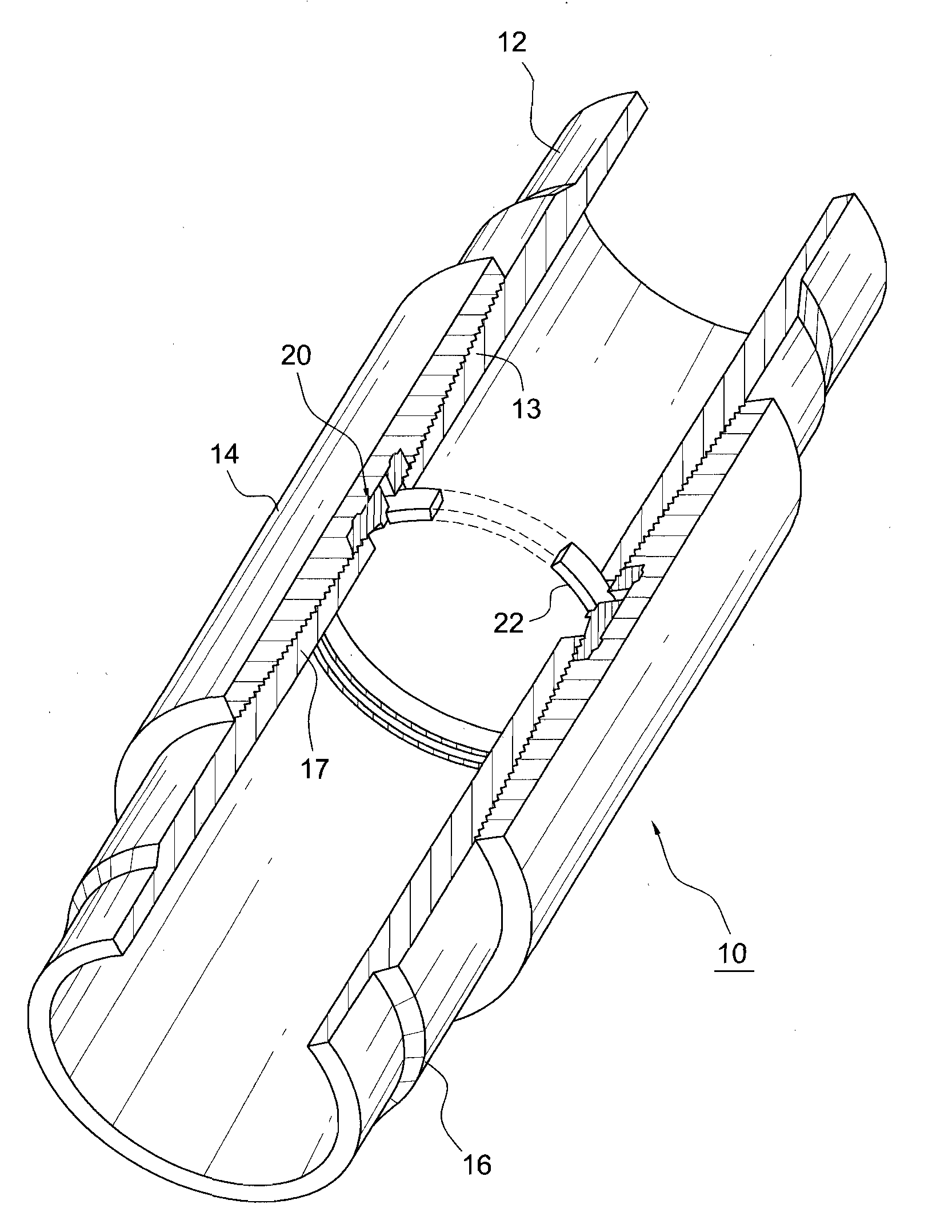
pipe. The “Teflon” body also includes outwardly directed ridges at longitudinally spaced apart locations that are of low height relative to the outer circumference of the central body but engage in
mating grooves in the opposing face of the
coupling to prevent longitudinal shifting of the seal when a pin end is torqued into position. To this end, a shaped tool
mating with the interior of the seal element may be inserted within the seal interior to prevent the formation of wrinkles in the seal as torque is applied to the pin and the seal is correspondingly deformed.
[0010]At the field site, the tubular elements with attached
coupling sleeves can then be assembled into a string. To this end, a new length of tubing is stabbed into open end of the coupling sleeve and tightened until it engages into the tapered wing at the field end side to a desired torque level. During torquing, the
external pressure ridges prevent longitudinal displacement of the ring body relative to the coupling sleeve, so the desired final geometric disposition of components is achieved, thus virtually eliminating the possibility of explosive decompression of the seal material.
[0011]In operation, internal gas pressures that are encountered may cause, over time,
permeation of the gases through the matrix of the “Teflon” until the gases build up in the small but adequate gas groove. If the tubing string is then removed from the well site, or the
internal pressure in the tubing is suddenly relieved, the gases which have permeated through the “Teflon” are readily able to flow in a
low impedance path from the gas groove through the radial ports and then to the interior of the tubing. Thus any differential gas pressures on the “Teflon” body and the “Peek” reinforcing ring are almost instantaneously relieved. Also during operations, minute amounts of fluid can work their way between the “Peek” ring and “Teflon” ring, passing through the
differential pressure elimination ports, then filling the gas groove and making contact with the steel surface at the center of the coupling sleeve. The form and fit of the internal
diameter of the “Teflon” seal and the external
diameter of the “Peek” ring allow the fluid in but eliminate any possibility of exit. Any corrosive activity that takes place between the Teflon ring and steel coupling internal diameter is also minute, resulting merely in the discoloration of the steel surface and no structural or mechanical damage to the steel coupling. Since the
fluid electrolytes cannot be circulated or otherwise renewed a dead corrosion
cell is established at the conclusion of one
ion exchange, and further corrosion is eliminated.
[0012]With repeated withdrawals and disassembly of the string, the relatively longer field end wing on the central body enables repeated makeovers. Each time the seal is reused the threaded pin end of the tubing can penetrate the field end wing to slightly greater depths, maintaining the sealing / corrosion barrier performance and
mechanical integrity as the desired operative API specified torque level is reached in each instance.

