
Internal combustion engine

a combustion engine and combustion chamber technology, applied in the direction of machines/engines, vibration suppression adjustments, inertia force compensation, etc., can solve the problems of adding to the load of the engine, arranged in a highly complex layou

Inactive Publication Date: 2011-09-01
HONDA MOTOR CO LTD
View PDF12 Cites 23 Cited by
  • Summary
  • Abstract
  • Description
  • Claims
  • Application Information

AI Technical Summary

Benefits of technology

[0004]In view of such problems of the prior art, a primary object of the present invention is to provide an internal combustion engine that can optimize the layout of gears for transmitting an output torque of a crankshaft to balancer shafts and drive shafts of engine auxiliary devices.
[0005]A second object of the present invention is to provide a light-weight and compact internal combustion engine that uses gears for transmitting an output torque of a crankshaft to balancer shafts and drive shafts of engine auxiliary devices.
[0007]The engine auxiliary device may consist of, not exclusive, a fuel pump, oil pump, alternator, generator, compressor or water pump. The gears typically consist of spur gears, but at least some of the gears may consist of gears other than spur gears without departing from the spirit of the present invention. As the fourth gear simply receives the engine torque from the first gear via one of the second gear and third gear, the fourth gear on the drive shaft of the auxiliary device is not subjected to the loading caused by the balancer shaft, and hence can be made of a compact and light-weight gear. Furthermore, this allows the various gears to be arranged in an efficient (in terms of the overall weight for the given mechanical strength requirements) and compact manner.
[0008]The engine may further comprise a fuel pump having a drive shaft located above the crankshaft, and actuated by the crankshaft via a gear train. Thereby, the fuel pump is located in the vicinity of the cylinder bank so that the length of the passage between the fuel pump and common rail or each fuel injection valve can be minimized. This also contributes to the compact and light-weight design of the engine.
[0009]According to a preferred embodiment of the present invention, the first gear and first transmission gear have a substantially same pitch diameter. In particular, the camshaft of the engine may be actuated by a rotary member located above the crankshaft via a timing chain or belt, and the rotary member is in turn actuated by the crankshaft via a gear train. Thereby, the timing chain or belt is required to have a relatively small length, and this contributes to the improvements in the synchronization of the camshafts with the crankshaft and the reliability of the engine. Typically, the rotary member actuated by the crankshaft via the timing chain or belt comprises a drive shaft of a fuel pump for pressurizing engine fuel.

Problems solved by technology

Particularly in the case of a diesel engine, some rotational fluctuations are inevitable, and this adds to the load of the engine.
Furthermore, a diesel engine includes a fuel pump for pressurizing the fuel to a high pressure, and this also applies a fluctuating load to the engine.
However, the various gears are arranged in a highly complex layout, and there is some room for improvement with respect to the optimization of the gear layout.

Method used


Image

  • Internal combustion engine
  • Internal combustion engine
  • Internal combustion engine

Examples


Embodiment Construction

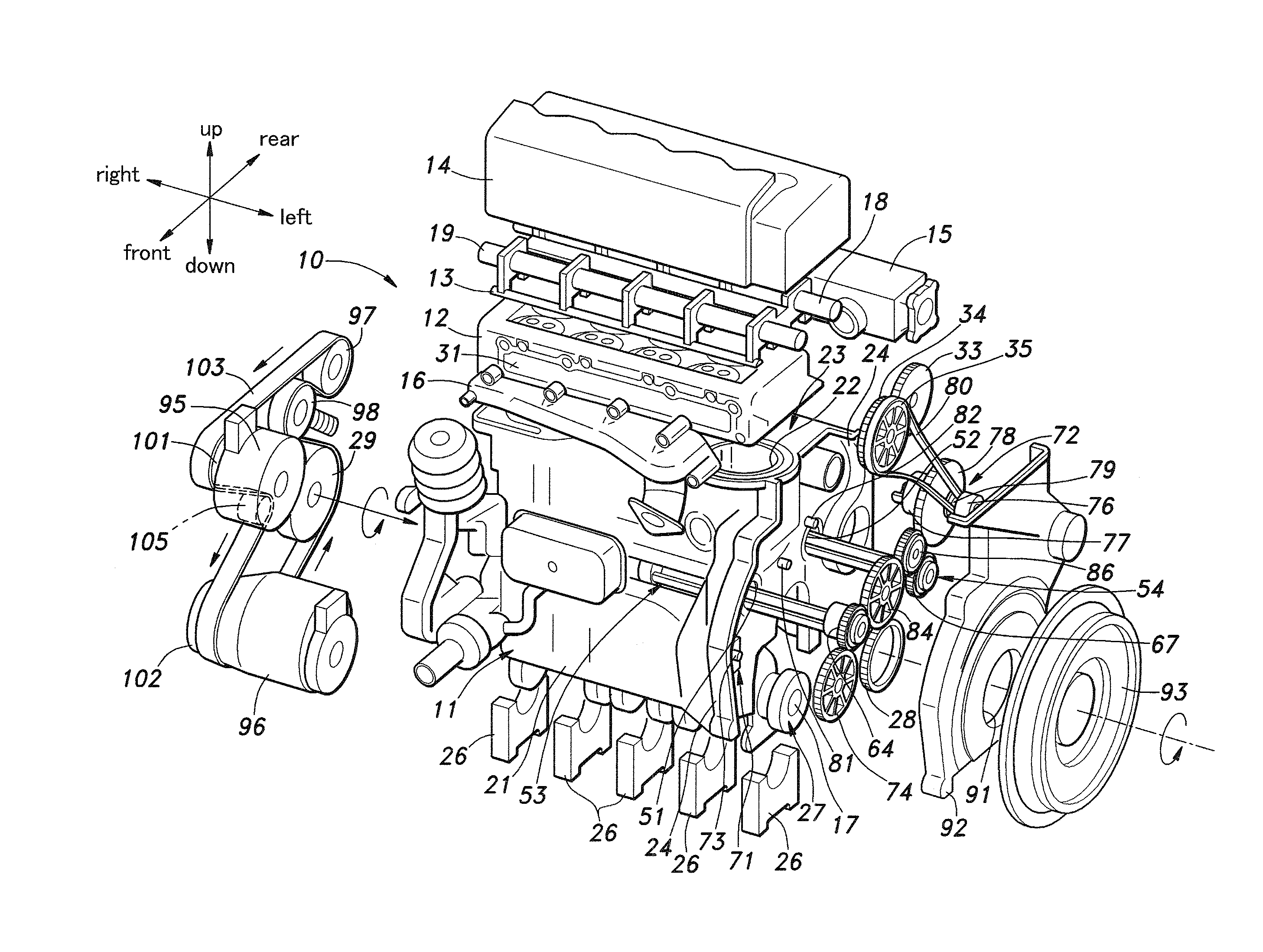
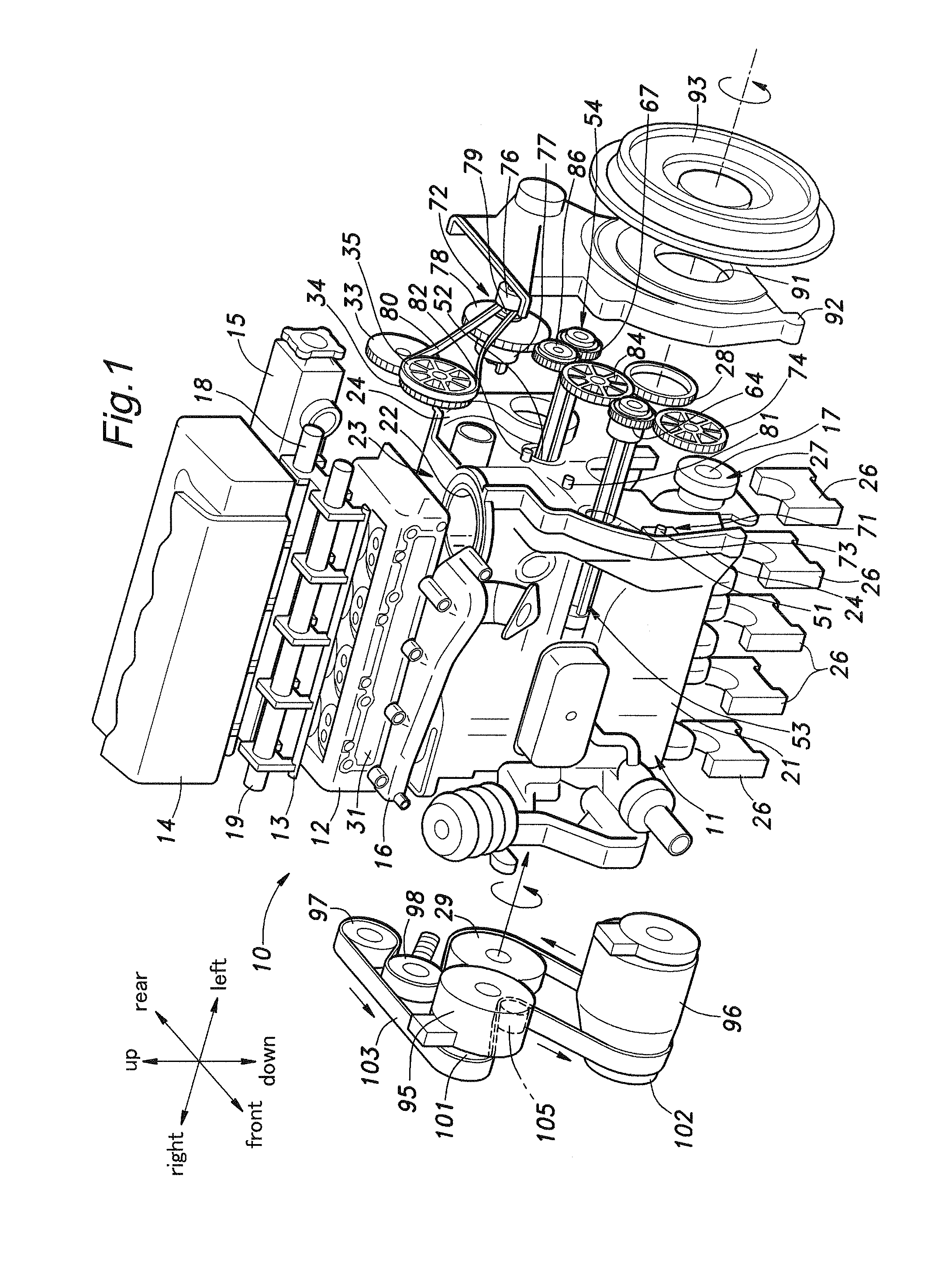
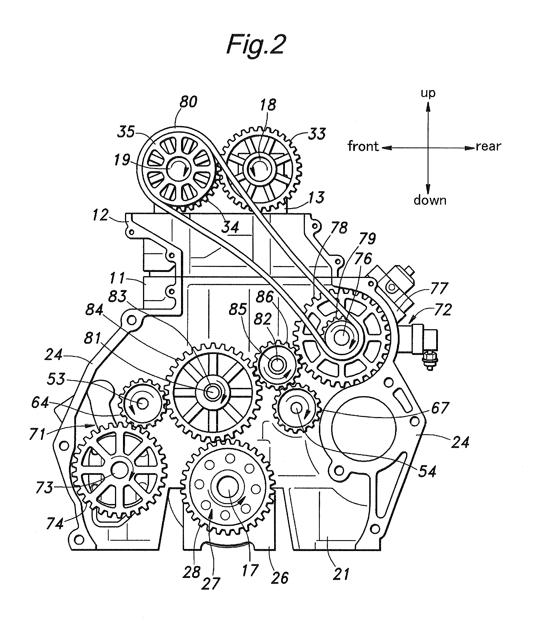
[0015]Referring to FIG. 1, an embodiment of the present invention in the form of a diesel engine is described in the following. The illustrated diesel engine 1 is laterally mounted on a vehicle body, and the directions in the following description are based on the understanding that the forward direction coincides with the forward direction of the vehicle as indicated in FIG. 1. The diesel engine 10 comprises a cylinder block 11, a cylinder head 12, a camshaft bearing holder 13, a cylinder head cover 14, an intake manifold 15, an exhaust manifold 16, a crankshaft 17, an intake camshaft 18, an exhaust camshaft 19 and an oil pan (not shown in the drawings), essentially in a conventional manner.

[0016]The cylinder block 11 includes a crankcase 21 which defines a chamber opening out in a downward direction, and an in-line bank 23 of four cylinders 22 provided above the crankcase 21. The left side of the cylinder block 11 is formed with a protruding wall 24 extending substantially over th...


PUM


Abstract

In an internal combustion engine having a pair of balancer shafts (53, 54), an engine torque is transmitted from a crank gear (28) to an oil pump gear (74) on a drive shaft (73) of an oil pump (71) via a first idler gear (84) and the first balancer shaft gear (64). The engine torque is also transmitted to a fuel pump (72) from the crank gear to a fuel pump gear (78) via the first idler gear and a second idler gear (86), and to the second balancer shaft gear (67) via the first idler gear and second idler gear. Alternatively, the engine torque may be transmitted to the fuel pump from the crank gear to the fuel pump gear via the first idler gear, second balancer shaft gear and second idler gear. As the oil pump gear is actuated by the crank gear via the first idler gear, the oil pump gear is not subjected to the loading caused by the balancer shaft, and hence can be made of a compact and light-weight gear. Furthermore, this allows the various gears to be arranged in an efficient (in terms of the overall weight for the given mechanical strength requirements) and compact manner.

Description

TECHNICAL FIELD[0001]The present invention relates to an internal combustion engine including a power transmission mechanism for transmitting a crankshaft output to balancer shafts and at least one engine auxiliary device.BACKGROUND OF THE INVENTION[0002]Dynamic balancers are effective in canceling imbalances in reciprocating engines, and typically include a pair balancer shafts each incorporated with an eccentric mass for counteracting the imbalance in the moving parts of the engine. When the engine accelerates or decelerates, each balancer shaft applies a load to the engine. Particularly in the case of a diesel engine, some rotational fluctuations are inevitable, and this adds to the load of the engine. Furthermore, a diesel engine includes a fuel pump for pressurizing the fuel to a high pressure, and this also applies a fluctuating load to the engine.[0003]The engine disclosed in JP 2004-245131A (patent document 1) uses a gear train, instead of the more conventional timing belt o...

Claims


Application Information

Patent Timeline
Patent Type & Authority Applications(United States)
IPC IPC(8): F16F15/22
CPCF16F15/265F02B67/06
Inventor KATAYAMA, GOICHIFUJIYOSHI, YOSHIHIROTAJIMA, YUTAKAYAMAMOTO, SHOICHI
Owner HONDA MOTOR CO LTD
Learn More