Electrically Conductive Composite Material
a composite material and electrically conductive technology, applied in the direction of non-conductive materials with dispersed conductive materials, synthetic resin layered products, fault locations, etc., can solve the problems of wire core failure, and detection of damage to the outer conductive layer
- Summary
- Abstract
- Description
- Claims
- Application Information
AI Technical Summary
Benefits of technology
Problems solved by technology
Method used
Image

Examples
example 1
Nickel-Coated Carbon Fiber Cloth
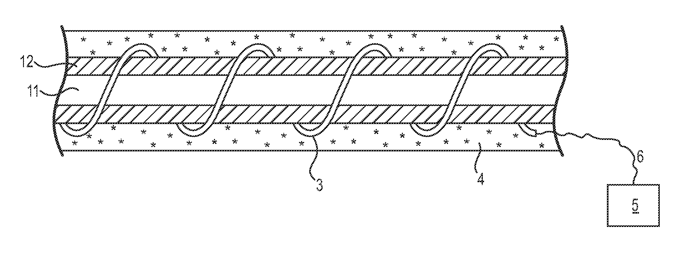
[0144]We found that in order to detect damage to the conductive layer 21, an electrical resistance of approximately 50 ohms was required over whatever distance was being monitored. An inherently conductive polyaniline was obtained with a resistance of 49 ohms per foot. But this was found difficult to reproduce for deposition onto a wire insulation layer.
[0145]Nickel-coated (nickelized) carbon cloths were obtained from Conductive Composites Company (Midway, Utah) and evaluated for detection layer applications.
[0146]Table 1 lists the conductivity measurements and amounts of nickel coating on the cloths. The carbon cloth squares were 5×5 inches, and conductivity was measured across the length of a square, over 5 inches. The uncoated cloth had a mass of 0.13 g.
TABLE 1Conductivity Measurements for Nickel-Coated Carbon Cloth.Milligrams of nickel coating per sheetConductivity (Ω / square)09101.5110.8350.2430.15
Polymer Coating of Nickelized Carbon Cloth.
[0147]S...
example 2
Nickel-Coated Carbon Fibers
[0150]Nickel-coated carbon fibers were obtained from various commercial vendors. These contain nickel coated onto a ribbon of carbon fibers via chemical vapor deposition (CVD). The fibers contained 2-63% nickel by weight. TGA showed that the nickel-coated fibers were stable to over 300° C. A 250-foot wire construct was prepared using 40%, 62%, and 63% nickel carbon (NiN—C) fibers. Strands of these fibers were wrapped around the inner insulation material of the wire using a tape wrap machine with 0, 25, 33, 50, and / or 66% ribbon overlap. One of two methods were employed to manufacture the outer insulation: (1) tape insulation material, i.e. Teflon, was wrapped over the NiN—C fibers and sintered at temperatures above 900° F. or (2) FEP insulation material was extruded over the NiN—C fibers using a horizontal single screw extruder. TGA analysis showed the nickel-coated fibers were stable to over 900° C. Using TDR, damage to the detection layer was detectable ...
example 3
Conductive Metal Tapes
[0151]Conductive metal tapes were wrapped at 0, 25, and 50% overlap onto the inner insulation layer of a standard wire type using a tape winding machine. One of two methods were employed to manufacture the outer insulation: (1) tape insulation material, i.e. Teflon, was wrapped over the metallic tape and sintered at temperatures above 900° F. or (2) FEP insulation was extruded over the metal tape using a horizontal single screw extruder. Tapes of copper or aluminum 3 mil thick were favorable based on their flexibility and conductivity. Improving draw tension of the tapes during wrapping eliminated the need for an adhesive layer.
PUM
| Property | Measurement | Unit |
|---|---|---|
| thickness | aaaaa | aaaaa |
| thick | aaaaa | aaaaa |
| thick | aaaaa | aaaaa |
Abstract
Description
Claims
Application Information
 - R&D
- Intellectual Property
- Life Sciences
- Materials
- Tech Scout
- Unparalleled Data Quality
- Higher Quality Content
- 60% Fewer Hallucinations
Browse by: Latest US Patents, China's latest patents, Technical Efficacy Thesaurus, Application Domain, Technology Topic, Popular Technical Reports.
© 2025 PatSnap. All rights reserved.Legal|Privacy policy|Modern Slavery Act Transparency Statement|Sitemap|About US| Contact US: help@patsnap.com