
Optical fiber scanning probe

a scanning probe and optical fiber technology, applied in the field of optical fiber scanning probes, can solve the problems of inconvenient production of disposable components, limited resolution, and far from optimal guidance methods, and achieve the effect of low cos

Inactive Publication Date: 2011-09-01
KONINKLJIJKE PHILIPS NV
View PDF9 Cites 20 Cited by
  • Summary
  • Abstract
  • Description
  • Claims
  • Application Information

AI Technical Summary

Benefits of technology

[0007]Hence, an improved optical probe would be advantageous, and in particular a less complicated and low cost optical probe providing a reasonable FOV would be advantageous.
[0008]In particular, it may be seen as an object of the present invention to provide an optical probe that solves the above-mentioned problems of the prior art with having a sufficient field of view and a simple and / or low cost lens system.
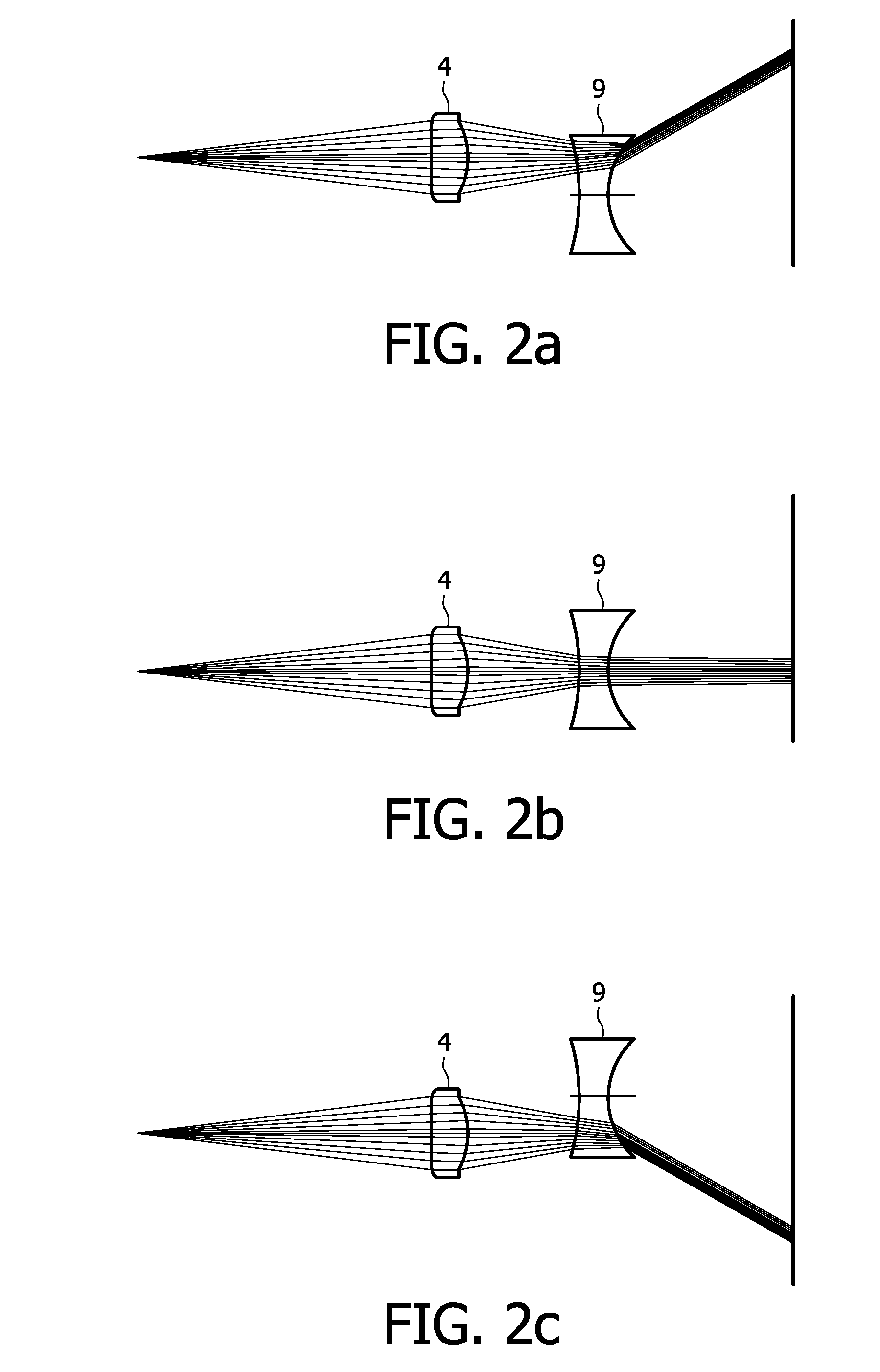
[0011]The optical probe may be used to (1) illuminate the region of interest and / or to (2) form an image of the region of interest. From a ray-tracing point of view these usages are equivalent, and both are relied upon in the following description of the involved optics, without a description using one of the usages indicating a limitation to this usage. Hence the first lens system may serve to couple radiation from the optical guide and focus it at an object plane at the region of interest and / or collect radiation from such object plane and couple it into the optical guide. When the distal end of the guide and first lens system are displaced by the actuation means, then the radiation from the first lens system is deflected in that direction. The second lens system serves to further deflect the radiation to / from the first lens system, preferably in the same direction as the displacement of the first lens system. Hence, in the first use the second lens system serves to increase the illuminated area at the object plane. In the second use, the second lens system serves to increase the field of view (FOV) of radiation coupled to the optical guide by the first lens system.
[0031]Aspherical lenses have the advantage of producing images in which spherical aberration is eliminated and optical abberation is reduced when compared to images produced by simple lens. Therefore a single aspheric lens can often replace a much more complex multi-lens system. This provides the advantage of reducing the complexity of the lens design resulting in smaller, lighter and possibly cheaper system.
[0033]The probe according to first aspect preferably comprises a transparent window inside the housing at its distal end. In one embodiment, the second lens system forms the transparent window at a distal end of the housing, thereby saving the required material use for the probe and reducing fabrication steps—both of which may lead to a cheaper probe.
[0034]It should further be mentioned that the optical probe according to the present invention is particularly suited for relative simple and large-scale manufacturing because of the lens system being displaceably mounted on the end portion optical guide. From a practical point of view, the production of lens systems in polymer material, which are made by molding and therefore allowing mass production, may lower the unit-price per probe and therefore present a viable approach towards an affordable disposable endoscope. This is especially important because an endoscope, a catheter or needle with the optical probe embedded will normally be disposed after a single use due to sanitary requirements.

Problems solved by technology

Although helpful, these methods of guidance are far from optimal.
The resolution is limited and, furthermore, these imaging modalities can in most cases not discriminate between benign and malignant tissue.
Most of these systems, e.g. relay lens system and fiber bundles, involve complicated optics making these systems expensive and hence not suitable for production of disposable components.
Also camera sensor in videoscope has the disadvantage that the image sensor must have a small lateral view, which makes these image sensors complicated and expensive as more common, and cheap technology, as in mobile phone cameras, cannot be applied.
Finally, fiber scanners located in front of a fixed lens system have the disadvantage that in order to a have a reasonable field of view (FOV) a complicated lens system is required in combination with a rather large stroke of the fiber end as described for example in US2005 / 0052753.
Thus far, none of the above approaches seems to be a viable road towards an affordable disposable endoscope with a reasonable field of view.
In summary, previously disclosed fiber-scanning systems with a reasonable field of view (FOV) applies complex and expensive lens systems making them expensive and disadvantageous for use in disposable optical probes.

Method used


Image

  • Optical fiber scanning probe
  • Optical fiber scanning probe
  • Optical fiber scanning probe

Examples


Embodiment Construction

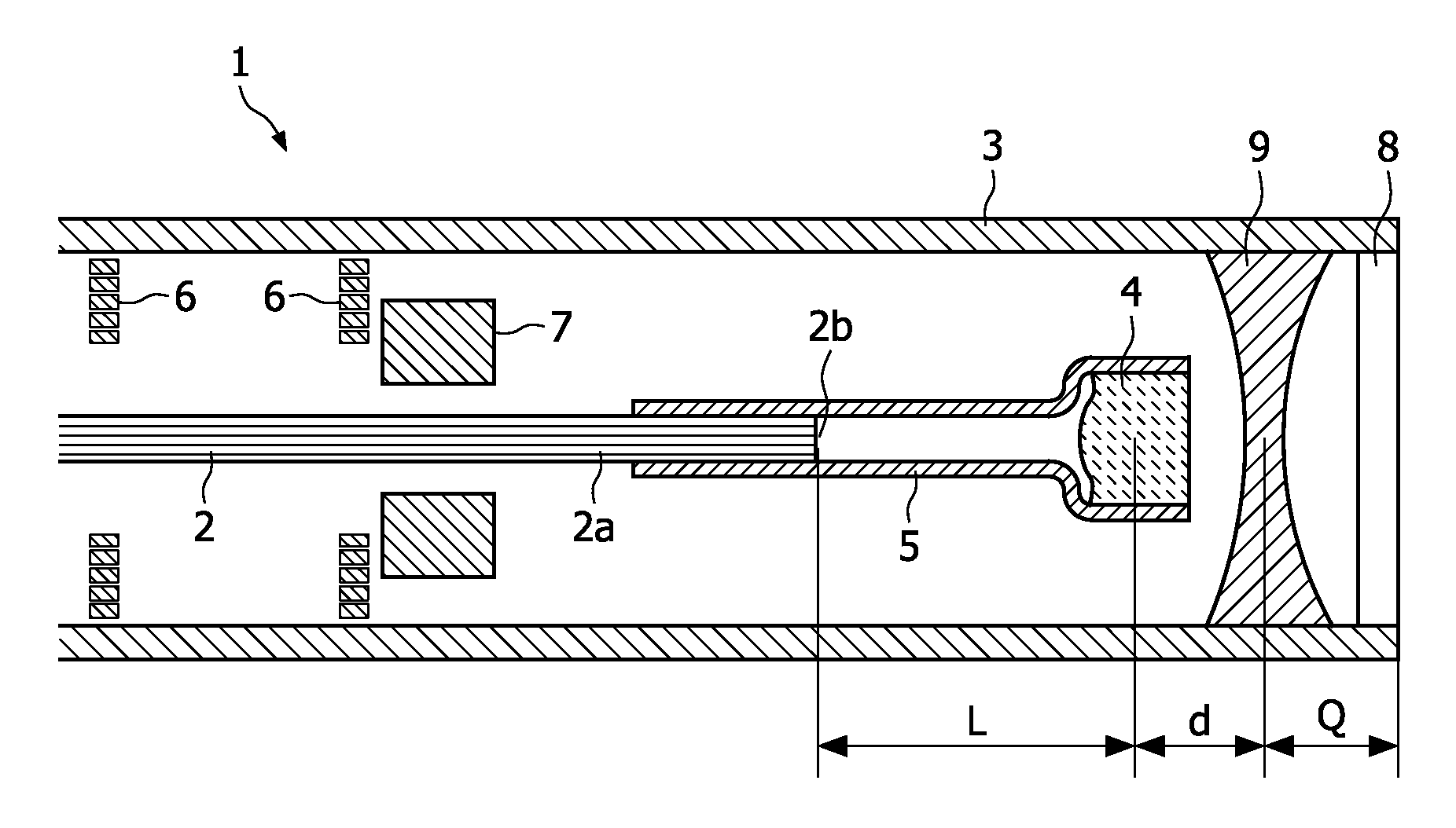
[0047]FIG. 1 shows a schematic cross-sectional drawing of an optical scanning probe according to the present invention. The optical probe 1 comprises an outer housing 3 holding an optical guide 2 with a first lens system 4 fastened at its distal end, preferably in a mechanical manner such as by an intermediate mount 5. The mount 5 holds the position of the distal end portion 2a of the optical guide 2 and the first lens system 4 in a fixed position relatively to each other by keeping the first lens system 4 centered on the longitudinal axis of the optical guide 2. The distance L between the optical exit 2b of the optical guide 2 and the first lens system 4 is typically significantly larger than a core diameter (df) of the optical guide 2.

[0048]The first lens system 4, which is rigidly coupled to the distal end portion of the optical guide 2a focus light coupled out from the optical guide 2. In FIG. 1, the first lens system is shown as a single lens for reason of clarity. The first le...


PUM


Abstract

The invention relates to optical probes for miniature applications, e.g. medical inspections and procedures or in industrial inspections, in particular a probe applying a confocal scanning-scanning endoscope. The probe comprises an optical guide (2), a first lens system mounted (4) on a distal end portion (2A) of the optical guide for focusing light from the optical guide, actuation means (6,7) for displacing the distal end portion and the first lens system to enable optical scanning, and a second lens system (9) fixed inside the probe to receive radiation from the first lens system. The second lens system is selected to enable a deflection of radiation from the first lens system in a direction corresponding to a direction of displacement of the first lens system by the actuation means. The second lens system can be a cheap negative lens, and the invention is thereby particularly useful for increasing the field of view (FOV) cheap, disposable optical probes.

Description

FIELD OF THE INVENTION[0001]The present invention relates to an optical probe suitable for miniature applications, e.g. in-vivo medical inspections and procedures or in industrial inspections, in particular a probe applying a confocal fiber-scanning endomicroscope. The invention also relates to a corresponding imaging system and a method for imaging with such an imaging system.BACKGROUND OF THE INVENTION[0002]For correct diagnosis of various diseases, e.g. cancer, biopsies are often taken. This can either be performed via a lumen of an endoscope or via needle biopsies. In order to find the correct position where the biopsy has to be taken, various imaging modalities are used such as X-ray, Magnetic Resonance Imaging (MRI) and ultrasound. For example in most of the cases of prostate cancer the biopsy is guided by ultrasound. Although helpful, these methods of guidance are far from optimal. The resolution is limited and, furthermore, these imaging modalities can in most cases not disc...

Claims


Application Information

Patent Timeline
IPC IPC(8): H04N5/225G02B26/10
CPCA61B1/07G02B23/2423G02B26/103A61B1/00096A61B1/00172G02B23/2469
Inventor HENDRIKS, BERNARDUS HENDRIKUS WILHELMUS
Owner KONINKLJIJKE PHILIPS NV
Learn More