Energy transfer system comprising a phase change material

Inactive Publication Date: 2011-09-15
SIEMENS AG
View PDF11 Cites 13 Cited by
  • Summary
  • Abstract
  • Description
  • Claims
  • Application Information

AI Technical Summary

Benefits of technology

[0042]This means that the described energy transfer system is capable of receiving electric energy from the external energy source. This makes it very easy to use a surplus of electricity, which has been produced for instance by wind turbine(s) or solar plant(s) at times with low demands, to charge the PCM with thermal energy such that the surplus of electricity can be stored as thermal energy. Even further, by controlling the frequency of the electrical energy applie

Problems solved by technology

However, unless sophisticated pressure vessels are used the maximum temperature of heat capacity storage in water is limited to 100° C.
Since for large capacity storage the cost of pressure vessels would be prohibitive, the use of water as a heat storage material is limited to a maximum temperature of 100° C. However, a maximum temperature of 100° C. is much too low in order to provide any useful thermodynamic efficiency of a heat engine, e.g. a steam turbo generator, which is to be operated on demand for release of the stored thermal energy.
Consequently, the benefits of the high heat capacity of water cannot be exploited in practice for high-volume energy storage.
However, solids generally have low heat capacity, and this leads to high volume requirements and to a low energy density.
However, molten salts have the drawback that they are generally not stable a

Method used


Image

  • Energy transfer system comprising a phase change material
  • Energy transfer system comprising a phase change material
  • Energy transfer system comprising a phase change material

Examples


first embodiment

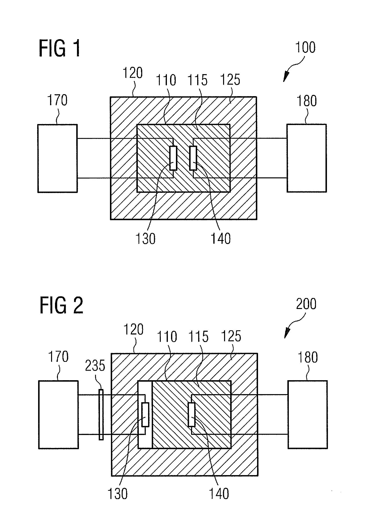
[0062]FIG. 1 shows the main components of an energy storage and energy transfer system 100 in accordance with the invention. A first container 110 comprising a PCM 115 is enclosed by a second container 120. The two containers 110, 120 are at least partly being thermally isolated from each other by a thermal isolation material 125.

[0063]At least one heat generation element 130 is receiving energy from an external energy source 170. The energy being received by the heat generation element 130 is used for heating the PCM 115. According to the embodiment described here the provided energy is electric energy, which is converted into thermal energy by the heat generation element 130. Further, at least one heat extraction element 140 is providing thermal energy to an external heat engine 180. This provided thermal energy is used for electricity production.

[0064]From the illustrated embodiment shown in FIG. 1 it can be seen that the heat generation element 130 is in direct physical connecti...
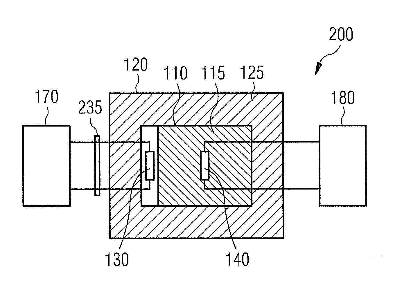
second embodiment

[0066]FIG. 2 shows the main components of an energy storage and energy transfer system 200 in accordance with the invention. From FIG. 2 it can be seen, that the heat generation element 130 is not in physical connection with the PCM 115. This will be an effective method of trans-ferring heat to the PCM 115 if the element 130 comprises at least one inductive heating element. In this case energy is preferably supplied to the heat generation element 130 as an AC-voltage. Thereby, the frequency of the AC may be the frequency of a utility grid. In order to adapt the applied frequency a frequency controller 235 is provided. With this frequency controller 235 the frequency of the AC voltage can be scaled to another frequency than the frequency of the utility grid. The frequency may also for various embodiments be alternated during operation.

[0067]For an even further embodiment of the invention, the heat generation element 130 may be directly connected to the utility grid. Thereby, a surplu...
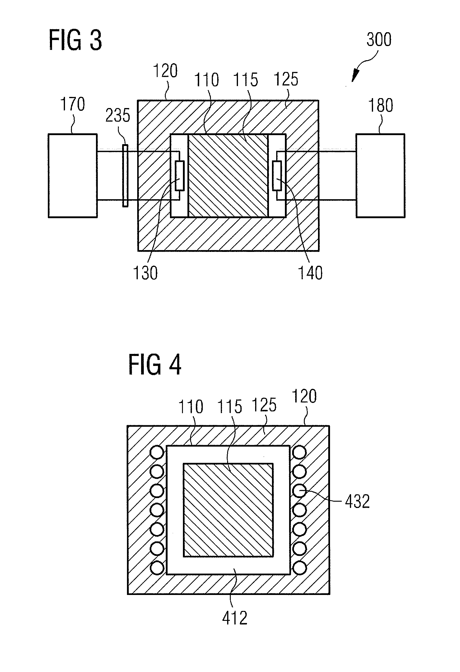
third embodiment

[0070]FIG. 3 shows the main components of an energy storage and energy transfer system 300 in accordance with the invention. As can be seen from FIG. 3, the at least one heat extraction element 140, which is used for extracting thermal energy from the PCM 115, can be located such that it is not in direct physically contact with the PCM 115.

[0071]FIG. 4 shows an induction coil 432, which may be integrated for instance in the thermal isolation material 125 of the energy storage and energy transfer system 300 shown in FIG. 3. The windings of the induction coil 432 are not in direct physical contact with the PCM 115 to be heated, but are separated by some refractory material 412.


PUM


Abstract

An energy transfer system for absorbing, temporarily storing and releasing energy is disclosed. The described energy transfer system comprises (a) a first container containing a Phase Change Material, (b) a heat generation element, which is connectable to an external energy source and which is capable of charging the Phase Change Material with thermal energy, wherein energy provided by the external energy source is used, and a heat extraction element, which is connectable to an external heat engine and which is capable of extracting thermal energy from the Phase Change Material, wherein the external heat engine is capable of converting the extracted thermal energy into electric energy. It is further described an energy transfer arrangement comprising two of such energy transfer systems, and a method for absorbing, temporarily storing and releasing energy.

Description

FIELD OF INVENTION[0001]The present invention relates to the field temporarily storing thermal energy. In particular the present invention relates to an energy transfer system for absorbing, temporarily storing and releasing energy. Further, the present invention relates to an energy transfer arrangement comprising two of such energy transfer systems. Furthermore, the present invention relates to a method for absorbing, temporarily storing and releasing energy.ART BACKGROUND[0002]The production of electric power from various types of alternative energy sources such as wind turbines, solar power plants and wave energy plants is not continuous. The production may be dependent on environmental parameters such as wind speed (for wind turbines), insulation (for solar power plant) and wave height and direction (for wave energy plants). There is very often little or no correlation between energy production and energy demand.[0003]One known approach to solve the problem of uncorrelated elec...

Claims


Application Information

Patent Timeline
IPC IPC(8): F01K21/00F28D20/02F28D17/00
CPCF28D20/021F28F2270/00F28D2020/0047Y02E60/145Y02E60/14F28D20/02
Inventor STIESDAL, HENRIK
Owner SIEMENS AG
Why Eureka
Try Eureka