Dielectric ceramic and laminated ceramic capacitor

a technology of laminated ceramic and dielectric ceramic, which is applied in the direction of fixed capacitors, alkaline earth titanates, electrical equipment, etc., can solve the problems of difficult to control the solid solubility with a high degree of accuracy, and the difficulty of achieving the balance between high temperature load and high temperature load, and achieves the effect of favorable temperature characteristics and high reliability

Active Publication Date: 2011-09-15
MURATA MFG CO LTD
View PDF5 Cites 19 Cited by
  • Summary
  • Abstract
  • Description
  • Claims
  • Application Information

AI Technical Summary

Benefits of technology

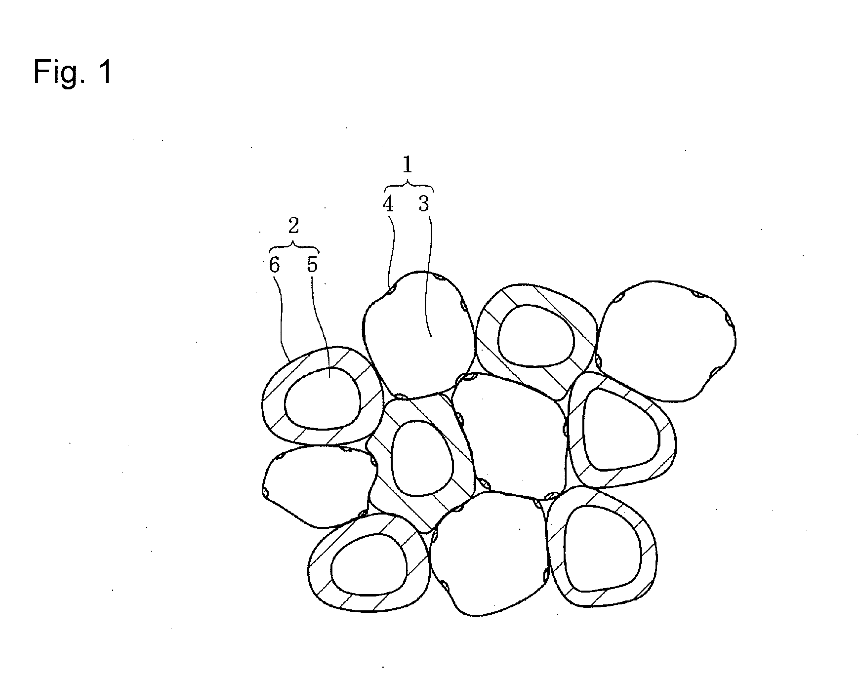
[0014]The present inventors have conducted earnest studies on the addition of a rare earth element to a barium titanate based compound and found that the crystal structure of a dielectric ceramic is made a mixed crystal structure including crystal grains containing only a minute amount of a rare earth element therein as a solid solution and including crystal grains of core-shell structure, in such a way that the respective ratios of the numbers of the both types of crystal grains fall within predetermined ranges, allows the achievement of a balance between high temperature load characteristics and temperature characteristics of capacitance even when the dielectric ceramic is reduced in layer thickness to less than 1 μm.
[0021]Specifically, even in the case of the reduction in layer thickness to less than 1 μm, dielectric ceramics can be obtained which have a long lifetime of 150 hours or more against the application of a direct-current voltage of 12.5 V at a high temperature of 150° C., and allow the achievement of a balance between high temperature load characteristics which satisfy the X5R characteristics of the EIA standards and temperature characteristics of capacitance.
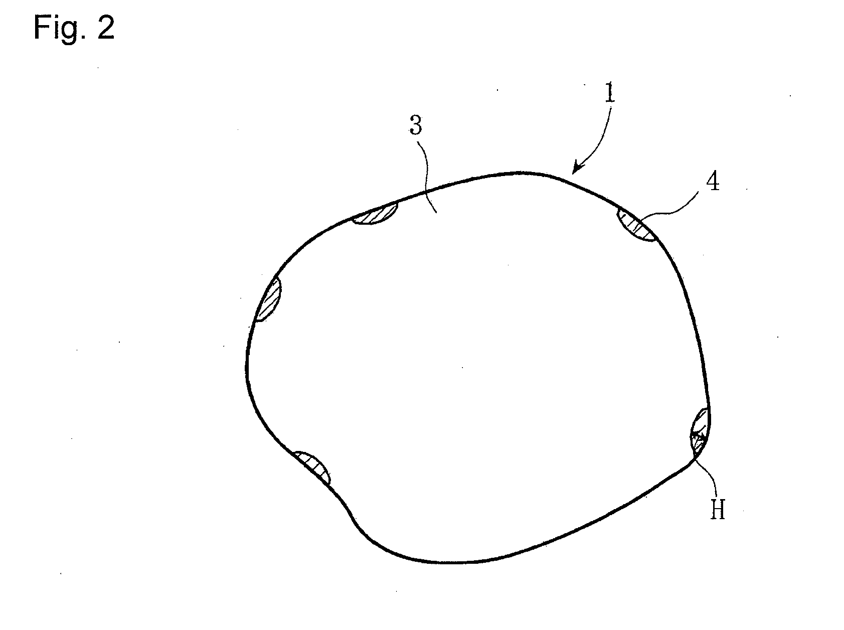
[0022]The first crystal grains have the rare earth element R with its solid solubility distance of 5 nm or less (including 0) in the main phase grain from the surface of the main phase grain toward the inside thereof, and furthermore, the shell section has a thickness of ⅛ or more and ⅜ or less the diameter of the main phase grain. Thus, the advantageous effect mentioned above can be produced easily.
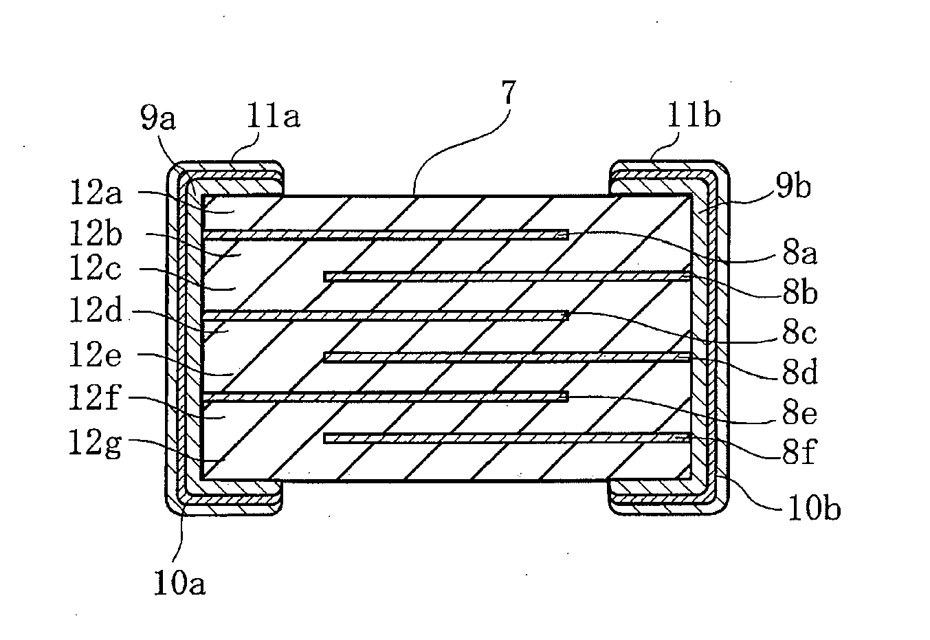
[0024]In the laminated ceramic capacitor according to the present invention, which includes a sintered laminated body obtained by alternately stacking and firing dielectric ceramic layers and internal electrodes and has external electrodes formed on both ends of the ceramic sintered body, the dielectric ceramic layers are formed from the dielectric ceramic described above. Thus, a laminated ceramic capacitor can be obtained which has high reliability and favorable temperature characteristics of capacitance.

Problems solved by technology

Although Japanese Patent Application Laid-Open No. 2002-80276 allows a laminated ceramic capacitor with a thickness on the order of 5 μm before firing to achieve a balance between high temperature load characteristics and temperature characteristics of capacitance, the laminated ceramic capacitor has the problem of difficulty in achieving the balance between high temperature load characteristics and temperature characteristics of capacitance when the dielectric ceramic layers are reduced in layer thickness to less than 1 μm.
Moreover, it is difficult to control the solid solubility with a high degree of accuracy even when a rare earth element is present as a solid solution in main phase grains.

Method used


Image

  • Dielectric ceramic and laminated ceramic capacitor
  • Dielectric ceramic and laminated ceramic capacitor
  • Dielectric ceramic and laminated ceramic capacitor

Examples


example 1

Production of Samples

[0079]BaCO3 and TiO2 were weighed in predetermined amounts as ceramic raw materials, and these weighed materials were charged into a ball mill along with PSZ balls and pure water for wet mixing and grinding the materials, and after drying, subjected to calcination at a temperature of 1050° C. for about two hours, thereby producing a main constituent powder composed of Ba1.007TiO3.

[0080]Next, the crystallinity of the main constituent powder was analyzed by an X-ray diffractometer (XRD). Then, the main constituent powder was sorted into a high-crystallinity main constituent powder and a low-crystallinity main constituent powder, and the both powders were mixed and weighed in a predetermined amount.

[0081]DyO3 / 2 was prepared as the specific rare earth element R, and MgO, MnO, V2O5, and SiO2 were prepared as other additive constituents. The additive powders were each weighed so as to provide DyO3 / 2: 1 part by mol, MgO: 0.7 parts by mol, MnO: 0.3 parts by mol, VO5 / 2: ...

example 2

[0099]BaCO3, TiO2, and CaCO3 were prepared as ceramic raw materials to produce a main constituent powder composed of (Ba1-xCax)mTiO2 (m is 0.960 to 1.030, and x is 0 to 0.20) in accordance with the same method and procedure as in Example 1.

[0100]Next, a rare earth element oxide RO3 / 2 (R is La, Ce, Pr, Nd, Sm, Eu, Gd, Tb, Dy, Ho, Er, Tm, Yb, Lu, or Y), as well as MgO, MnO, VO5 / 2, SiO2, and LiO1 / 2 were prepared as additive constituents.

[0101]Then, the main constituent powder and the additive constituents were weighed so as to provide molar ratios as shown in Table 2, and the weighed main constituent powders and additive constituents were used to provide ceramic raw material powders in accordance with the same method as in Example 1.

[0102]These ceramic raw material powders were used to produce ceramic green sheets such that dielectric ceramic layers had a thickness of 0.8 μm after firing, in accordance with the same method and procedure as in Example 1, and a firing treatment was furth...


PUM

PropertyMeasurementUnit
thicknessaaaaaaaaaa
thicknessaaaaaaaaaa
temperatureaaaaaaaaaa

Abstract

A dielectric ceramic (and capacitor containing it) balancing high temperature load characteristics and temperature characteristics of capacitance even when layer thickness is less than 1 μmhas a mixture of different crystal grains containing a barium titanate compound as the main constituent. The first crystal grains can contain rare earth element solid solution region lat the surface layer section. The second crystal grains have a core-shell structure including a shell section having a rare earth element solid solution present. The first and second crystal grains are 12% to 84% f and 16% to 88%, respectively, of the total number of crystal grains.

Description

BACKGROUND OF THE INVENTION[0001]1. Field of the Invention[0002]The present invention relates to a dielectric ceramic and a laminated ceramic capacitor, and more particularly, relates to a dielectric ceramic suitable for a laminated ceramic capacitor which has small size and high capacitance, and a laminated ceramic capacitor manufactured with the use of the dielectric ceramic.[0003]2. Description of the Related Art[0004]Conventionally, barium titanate based compounds with high dielectric constants have been widely used as ceramic materials for use in laminated ceramic capacitors.[0005]With the developments in electronics technology in recent years, the reduction in size and the increase in capacitance for laminated ceramic capacitors have been progressed rapidly.[0006]The laminated ceramic capacitor has dielectric ceramic layers and internal electrodes which are stacked alternately, and has external electrodes formed on both ends of a ceramic sintered body obtained by a firing trea...

Claims


Application Information

Patent Timeline
Patent Type & Authority Applications(United States)
IPC IPC(8): H01G4/12C04B35/468
CPCC01G23/006C04B2235/79C01P2006/40C04B35/4682C04B35/62685C04B35/62815C04B2235/3203C04B2235/3206C04B2235/3208C04B2235/3215C04B2235/3224C04B2235/3225C04B2235/3227C04B2235/3229C04B2235/3232C04B2235/3236C04B2235/3239C04B2235/3262C04B2235/656C04B2235/6582C04B2235/6584C04B2235/6588H01G4/1227C04B2235/80C04B2235/3418C01P2004/82C04B35/468C04B35/50H01G4/12
Inventor MURAKI, TOMONORINAKAMURA, TOMOYUKIMATSUDA, MAKOTOSHIOTA, AKIHIRO
Owner MURATA MFG CO LTD
Why Eureka
Try Eureka