Tandem angular ball bearing

a technology of angular ball bearings and ball bearings, which is applied in the direction of bearings, shafts and bearings, rotary bearings, etc., can solve the problems of large dynamic torque (rotational resistance), large load capacity, and the possibility of secureness, so as to reduce the life of balls, prevent excessive vibration or noise, and prevent damage

Inactive Publication Date: 2011-09-15
NSK LTD
View PDF10 Cites 11 Cited by
  • Summary
  • Abstract
  • Description
  • Claims
  • Application Information

AI Technical Summary

Benefits of technology

[0041]With one embodiment of the tandem angular ball bearing of the present invention, when assembled between the inner peripheral surface of a fixed portion such as a support section formed inside a housing such as a differential casing, and the outer peripheral surface of a rotating shaft, it is possible to prevent damage such as scratching from occurring to the rolling surfaces of the balls to an extent that would excessively decrease the life of the balls. In other words, in the tandem angular ball bearing of the present invention, when combining the outer ring that is securely fitted on the inside of the stationary portion and the inner ring that is securely fitted around the rotating shaft, the entire portions of the inner peripheral surface of the outer ring and the outer peripheral surface of the inner ring that the rolling surfaces of the balls can come in contact with are smooth surfaces with no sharp corners. Therefore, when performing the assembly work, damage to the rolling surfaces of the balls such as scratching does not occur even when a rolling surface of a ball forcibly hits against or strongly rubs against any portion of the inner peripheral surface of the outer ring or outer peripheral surface of the inner ring. Consequently, during operation of the tandem angular ball bearing, it is possible to prevent excessive vibration or noise due to damage to the rolling surfaces of the balls, and thus it is possible to sufficiently maintain the durability of the tandem angular ball bearing.
[0042]In the case of another embodiment of the tandem angular ball bearing of the present invention, groove shoulder sections are provided on both sides in the axial direction of at least one of the outer ring raceways of both outer ring raceway on the large-diameter side or small-diameter side. Therefore, for example, by using the tandem angular ball bearing of the present invention in an apparatus to which lubrication oil is supplied only during operation, such as in some differential gears, lubrication oil is collected in the bottom end sections of the outer ring raceway(s), from among both outer ring raceways, having groove shoulder sections on both sides in the axial direction. This enables good initial lubrication in both rows when restarting operation. In other words, when there are groove shoulder sections on both sides in the axial direction of both outer ring raceways, lubrication oil is collected in the bottom end sections of both outer ring raceways on the large-diameter side and small-diameter side. Therefore, when operation is restarted, there is good initial lubrication due to the lubrication oil that is collected in both of these bottom end sections. Moreover, when there is a groove shoulder section on both sides in the axial direction of only one of the outer ring raceways from among both outer ring raceways on the large-diameter side and small-diameter side, when operation is stopped, lubrication oil is collected in the bottom end section of only one outer ring raceway. However, as operation is restarted, some of the lubrication oil that is collected in the bottom end section of that one outer ring raceway is pushed to the outside by the balls rolling in that outer ring raceway, and enters into the other outer ring raceway, so it is possible to have good initial lubrication in not only the row that includes the one outer ring raceway, but also in the row that includes the other outer ring raceway.
[0043]Furthermore, in a preferred embodiment, by combining the outer ring, both cages on the large-diameter side and small-diameter side, and the balls that form both ball rows on the large-diameter side and small-diameter side into a state that is the same as the completely assembled tandem angular ball bearing, these parts can be treated as a single outer ring side assembly.
[0044]In this case, the tandem angular ball bearing is divided into and treated as two elements; an outer ring side assembly and an inner ring. Therefore, by shipping this outer ring side assembly after being assembled by the bearing manufacturer, at the assembly site of various kinds of rotating mechanical equipment such as a differential apparatus, the work of assembling the tandem angular ball bearing of the present invention in the location where the bearing will be used can be performed easily.
[0045]Particularly, in the case of the present invention, with the outer ring side assembly assembled, the plurality of balls is placed on the inner-diameter side of the outer ring. Therefore, it is possible to avoid the problem of the balls being damaged by hitting against other parts while being transported before assembling the tandem angular ball bearing.

Problems solved by technology

It is well known in the field of rolling bearings, however, that in conical roller bearings, the load capacity is larger than in ball bearings, however, the dynamic torque (rotational resistance) also becomes large.
However, when assembled so that the component members of the ball bearing 1 do not separate from each other, it is not possible to securely fit the outer ring 5 in the support hole 22, and similarly it is not possible to securely fit the inner ring 6 around the pinion shaft 3 with an interference fit.
When putting the outer ring 5 and inner ring 6 together, these rough surface or corner sections powerfully strike against or strongly rub against part of the rolling surfaces of the balls 7, so there is a possibility that damage such as scratches will occur to the rolling surfaces.
The occurrence of this kind of damage makes it easy for large vibration or noise to occur during operation of the differential gear, and become a cause of an excessive decrease in the life of the balls, and thus there is a possibility that the durability of the tandem angular ball bearing will be adversely affected.
The first problem is caused by there not being groove shoulder sections in the portions on the one side in the axial direction of the outer ring raceways 10, 11 on the large-diameter side and small-diameter side.
Therefore, when operation is restarted, there is a problem in providing good initial lubrication.
In other words, there is a problem that before assembling the tandem angular ball bearing, it is easy for the balls 7 of the inner ring side assembly 31 to bump against other parts while being transported, making it easy for damage such as scratches and the like to occur on the rolling surfaces of the balls 7.
These problems are also problems linked to a decrease in durability of the tandem angular ball bearing, so there is a large need for these problems to be solved.
However, in known literature, including Patent Documents 1 to 6, nothing is disclosed about technology for preventing damage to the rolling surfaces of the balls during assembly of a tandem angular ball bearing, and currently problems such as described above have not been sufficiently solved.

Method used


Image

  • Tandem angular ball bearing
  • Tandem angular ball bearing
  • Tandem angular ball bearing

Examples


example 1

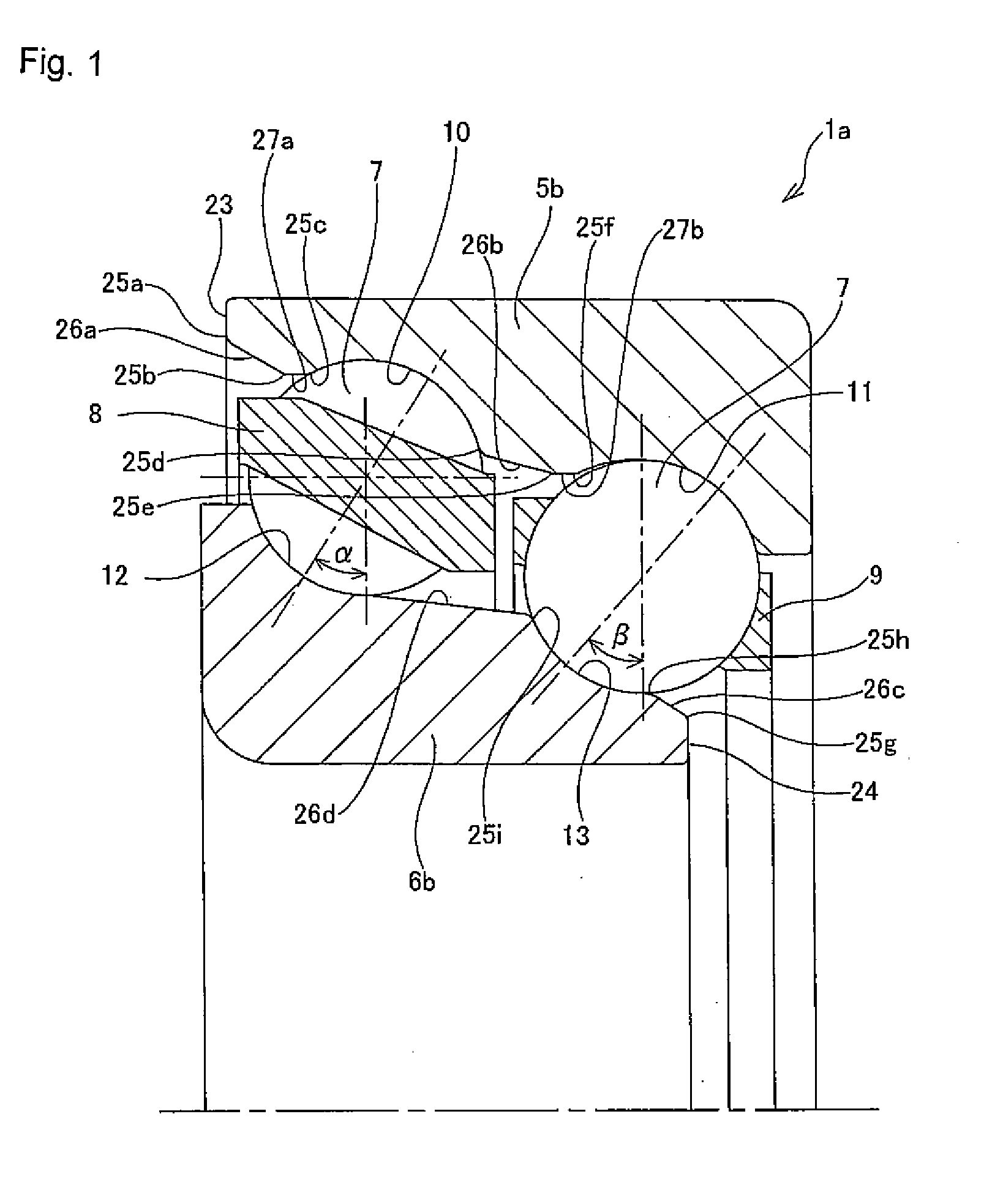
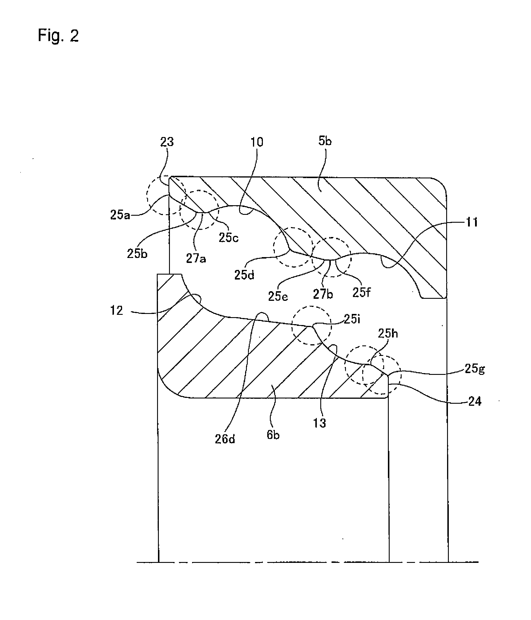
[0063]FIGS. 1 to 5 illustrate a first example of the present invention. The ball bearing 1a of this example of a tandem angular ball bearing comprises an outer ring 5b, and inner ring 6b, a plurality of balls 7 and a pair of cages 8, 9. The outer ring 5b has two rows of angular type outer ring raceways 10, 11 having different inner diameters formed around the inner peripheral surface thereof. The inner ring 6b is located on the inner diameter side of the outer ring 5b such that it is concentric with the outer ring 5b, and has two rows of angular type inner ring raceways 12, 13 having different outer diameters formed around the outer peripheral surface thereof in the portion that faces the outer ring raceways 10, 11. During operation, a thrust load is applied between the outer ring 5b and inner ring 6b such that it presses the outer ring 5b toward the left in FIG. 1, and similarly presses the inner ring 6b toward the right. When assembled in a differential gear, the large-diameter si...

example 2

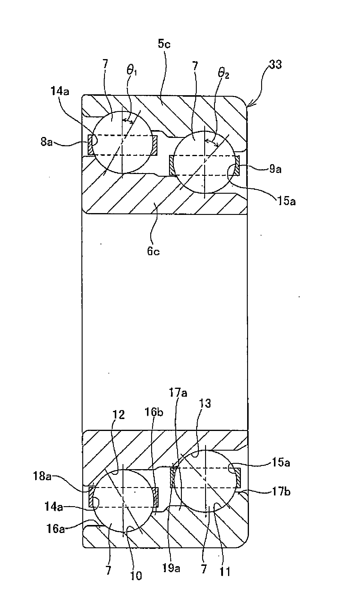
[0079]FIGS. 6 to 9 illustrate a second example of the present invention. The tandem angular ball bearing of this example comprises an outer ring 5c, an inner ring 6c, large-diameter side and small-diameter side cages 8a and 9a, and a plurality of balls 7 in a large-diameter side row and small-diameter side row. Double-row angular type large-diameter side and small-diameter side outer ring raceways 10, 11 having different inner diameters are formed around the inner peripheral surface of the outer ring 5c. Double-row angular type large-diameter side and small-diameter side inner ring raceways 12, 13 having different outer diameters are formed around the outer peripheral surface of the inner ring 6e. Cages 8a, 9b on the large-diameter side and small diameter side have a complete ring shape, and have pockets 14a, 15a at a plurality of locations uniformly spaced in the circumferential direction thereof. The balls 7 of the large-diameter side ball row are held inside the pockets 14a of th...

example 3

[0087]FIGS. 10 and 11 illustrate a third example of the present invention. In the case of this example, the shape of part of the outer ring 5d and the cage 8b on the large-diameter side differs from that of the second example described above. In other words, in this outer ring 5d, groove shoulder sections 16a, 16b, 17b are formed in only the portion on both sides in the axial direction of the outer ring raceway 10 on the large-diameter side, and the portion on the other side in the axial direction of the outer ring raceway 11 on the small-diameter side, and there is no groove shoulder section in the portion on the one side in the axial direction of the outer ring raceway 11 on the small-diameter side. Moreover, in the cage 8b on the large-diameter side, a inward-looking flange shaped brim section 34 is formed on the end section of the other end in the axial direction, and the outside surface of this brim section 34 is made to face in the axial direction the surface on the one end in...


PUM


Abstract

A tandem angular ball bearing is provide that prevent damage from occurring to the rolling surfaces of the balls during assembly and transport to an extent that would cause an excessive decrease in life of the balls, and that can maintain excelled durability without the occurrence of excessive vibration and noise during operation. In order to accomplish this, the entire portion of the inner peripheral surface of an outer ring (5b) from a small-diameter side outer ring raceway (11) to the continuous section (25a) that is continuous with the end surface (23) on the large inner diameter side of the outer ring (5b), and the entire portion of the outer peripheral surface of an inner ring (6b) from a large-diameter side inner ring raceway (12) to the continuous section (25g) that is continuous with the end surface (14) on the small outer-diameter side of the inner ring (6b) are polished smooth surfaces having no indifferentiable corner sections in the cross-section shape. Moreover, the outer ring (5c) comprises groove shoulder sections (16a, 16b, 17a, 17b) in at least one of the portion on one side in the axial direction of the large-diameter side outer ring raceway (10), and the portion on the one side in the axial direction of the small-diameter side outer ring raceway (11), and in the portion on the other side in the axial direction of the large-diameter side outer ring raceway (10) and in the portion on the other end in the axial direction of the small-diameter side outer ring raceway (11).

Description

TECHNICAL FIELD[0001]The present invention relates to a tandem angular ball bearing that is installed in rotating mechanical equipment such as a differential gear for an automobile or transfer equipment, and supports a rotating shaft that rotates in a state of a radial load and a thrust load being applied.RELATED ART[0002]Various construction for supporting a pinion shaft of a differential gear for an automobile inside a differential casing such that it can rotate freely is widely known as disclosed in Patent Documents 1 to 6. During operation of a differential apparatus of an automobile, large radial loads and thrust loads are simultaneously applied to the pinion shaft, so it is necessary to use a bearing for supporting the pinion shaft that has sufficiently large load capacity in both the radial and thrust directions. Therefore, as disclosed in Patent Document 1 for example, a pair of back-to-back arrangement conical roller bearings is used, the directions of the contact angles th...

Claims


Application Information

Patent Timeline
Patent Type & Authority Applications(United States)
IPC IPC(8): F16C19/18
CPCF16C19/182F16C43/06F16C2361/61F16C33/583F16C33/64F16C19/548F16C2240/34
Inventor TANOUE, YASUSHITANAKA, TAKANORIMAEJIMA, HIROKIHAYASHI, YOSHITAKAABE, KENICHIYUKAWA, KINJISAITO, TOMOHARU
Owner NSK LTD
Why Eureka
Try Eureka