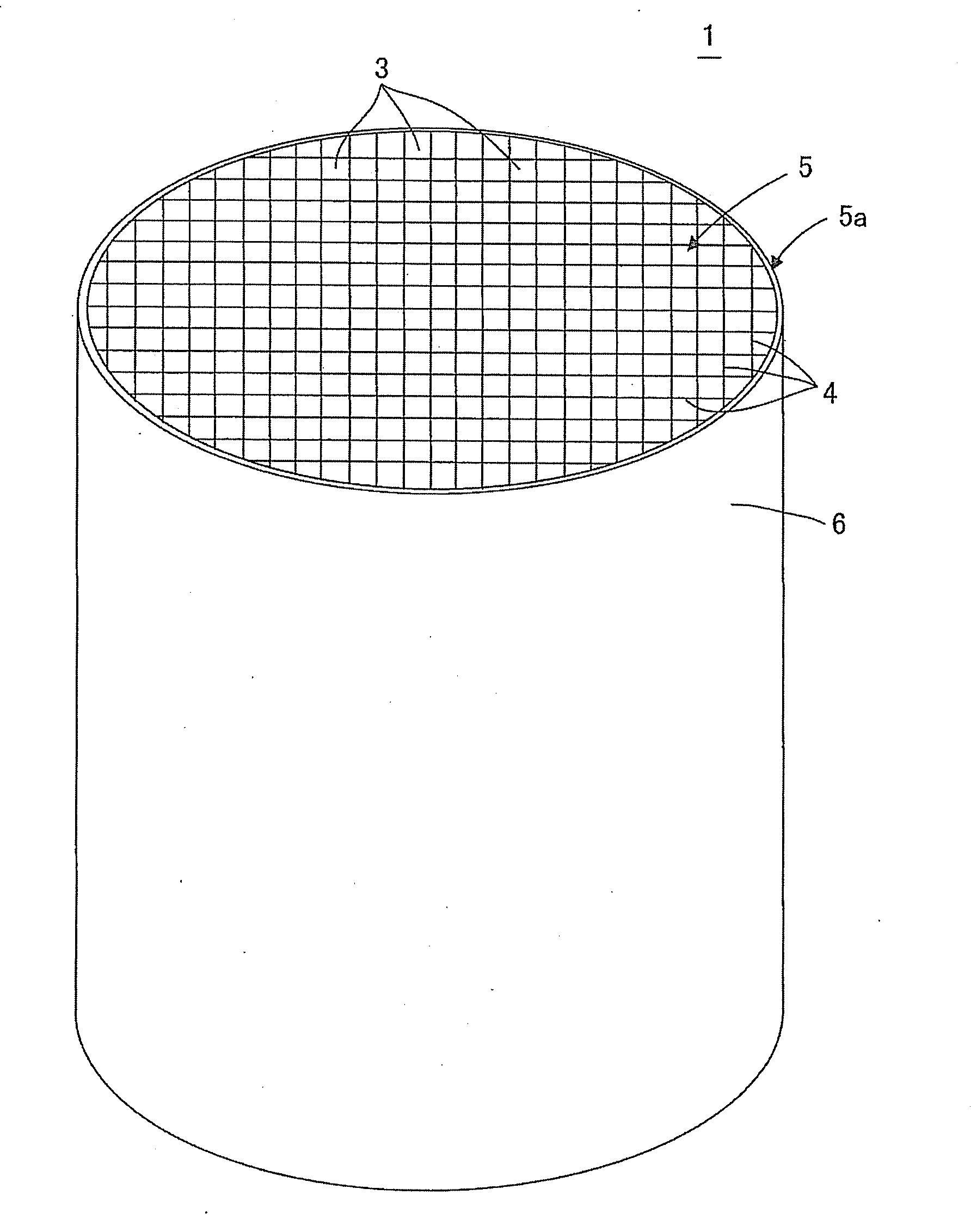
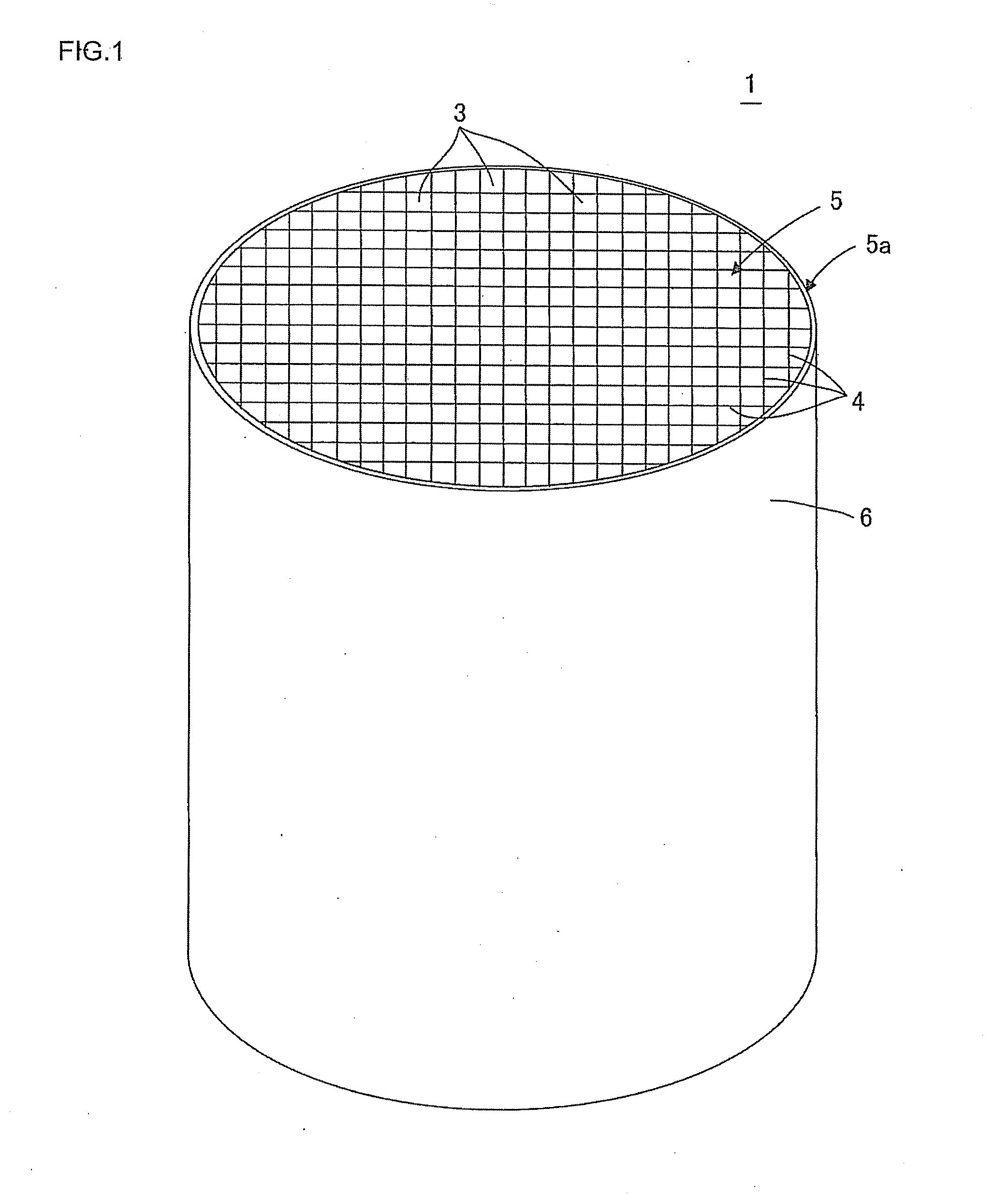
Outer periphery-coating material, outer periphery-coated honeycomb structure and process for production thereof
a technology of periphery coating and honeycomb, which is applied in the direction of metal/metal-oxide/metal-hydroxide catalyst, machine/engine, printing, etc., can solve the problems of high labor intensity, unreadable important information, and poor non-developed portions, and achieve excellent color contrast between color-developed portions and portions of no color development. , the effect of satisfying the color developmen
- Summary
- Abstract
- Description
- Claims
- Application Information
AI Technical Summary
Benefits of technology
Problems solved by technology
Method used
Image

Examples
example 1
[0108]There were mixed 100 parts by mass of a powder for cordierite formation as a ceramic powder, 200 parts by mass of silicon carbide as a metal carbide powder to function as a laser-coloring powder, 76 parts by mass of colloidal silica as an inorganic binder, and water as a dispersing medium, to prepare an outer periphery-coating material. Incidentally, water was used in an amount of 22 parts by mass relative to 100 parts by mass of the total of the ceramic powder and the laser-coloring powder (the metal carbide powder) in the outer periphery-coating material. The outer periphery-coating material further contained 0.15 part by mass of an organic binder and 0.9 part by mass of a clay relative to 100 parts by mass of the total of the ceramic powder and the laser-coloring powder. The thus-constituted outer periphery-coating material had a viscosity of 200 dPa·s.
[0109]Incidentally, CMC (carboxymethyl cellulose) was used as the organic binder. Bentonite was used as the clay.
[0110]The ...
examples 2 to 5
[0120]Outer periphery-coated honeycomb structures were produced in the same manner as in Example 1 except that the amount of silicon carbide used in the outer periphery-coating material was changed as shown in Table 1. Laser printing was conducted on the outer surface of each outer periphery-coated honeycomb structure in the same manner as in Example 1, and each printed portion was evaluated for durability and tested for readability of printed bar code. The results are shown in Table 1.
example 6
[0121]An outer periphery-coated honeycomb structure was produced in the same manner as in Example 1 except that an aluminum nitride powder was used as the laser-coating powder used in the outer periphery-coating material. Laser printing was conducted on the outer surface of the outer periphery-coated honeycomb structure obtained, in the same manner as in Example 1, and the printed portion was evaluated for durability and tested for readability of printed bar code. The results are shown in Table 1.
PUM
| Property | Measurement | Unit |
|---|---|---|
| particle diameter | aaaaa | aaaaa |
| particle diameter | aaaaa | aaaaa |
| particle diameter | aaaaa | aaaaa |
Abstract
Description
Claims
Application Information
 - R&D
- Intellectual Property
- Life Sciences
- Materials
- Tech Scout
- Unparalleled Data Quality
- Higher Quality Content
- 60% Fewer Hallucinations
Browse by: Latest US Patents, China's latest patents, Technical Efficacy Thesaurus, Application Domain, Technology Topic, Popular Technical Reports.
© 2025 PatSnap. All rights reserved.Legal|Privacy policy|Modern Slavery Act Transparency Statement|Sitemap|About US| Contact US: help@patsnap.com