Ferrite composition and electronic component

a technology of ferrite and composition, applied in the direction of nickel compounds, magnets, iron compounds, etc., can solve the problems of difficult to perform a lower temperature firing, difficult to achieve fact, and not considered the temperature characteristic of magnetic permeability, etc., to achieve good superposed direct current characteristic, good initial permeability, good temperature characteristic of initial permeability

Inactive Publication Date: 2011-09-22
TDK CORPARATION
View PDF6 Cites 7 Cited by
  • Summary
  • Abstract
  • Description
  • Claims
  • Application Information

AI Technical Summary

Benefits of technology

[0013]The present invention has been made by considering such situation, and a purpose of the invention is to provide a ferrite composition having good initial permeability, good superposed direct current characteristic and comparatively good temperature characteristic of the initial permeability, and achieving low temperature firing, and an electronic component having the ferrite composition.

Problems solved by technology

However, in the Japanese Patent Publication No. 2005-145781, a temperature characteristic of the magnetic permeability is not considered at all.
However, that has been in fact difficult to be achieved.
Also, in the Japanese Patent Publication No. 2005-213092, in addition that the temperature characteristic of the magnetic permeability is not considered at all, and a firing temperature is 1000° C. or more, it was difficult to perform a lower temperature firing.

Method used


Image

  • Ferrite composition and electronic component
  • Ferrite composition and electronic component
  • Ferrite composition and electronic component

Examples


examples

[0066]Below, the present invention will be explained based on further detailed examples, however, the present invention is not limited to these examples.

experiment 1

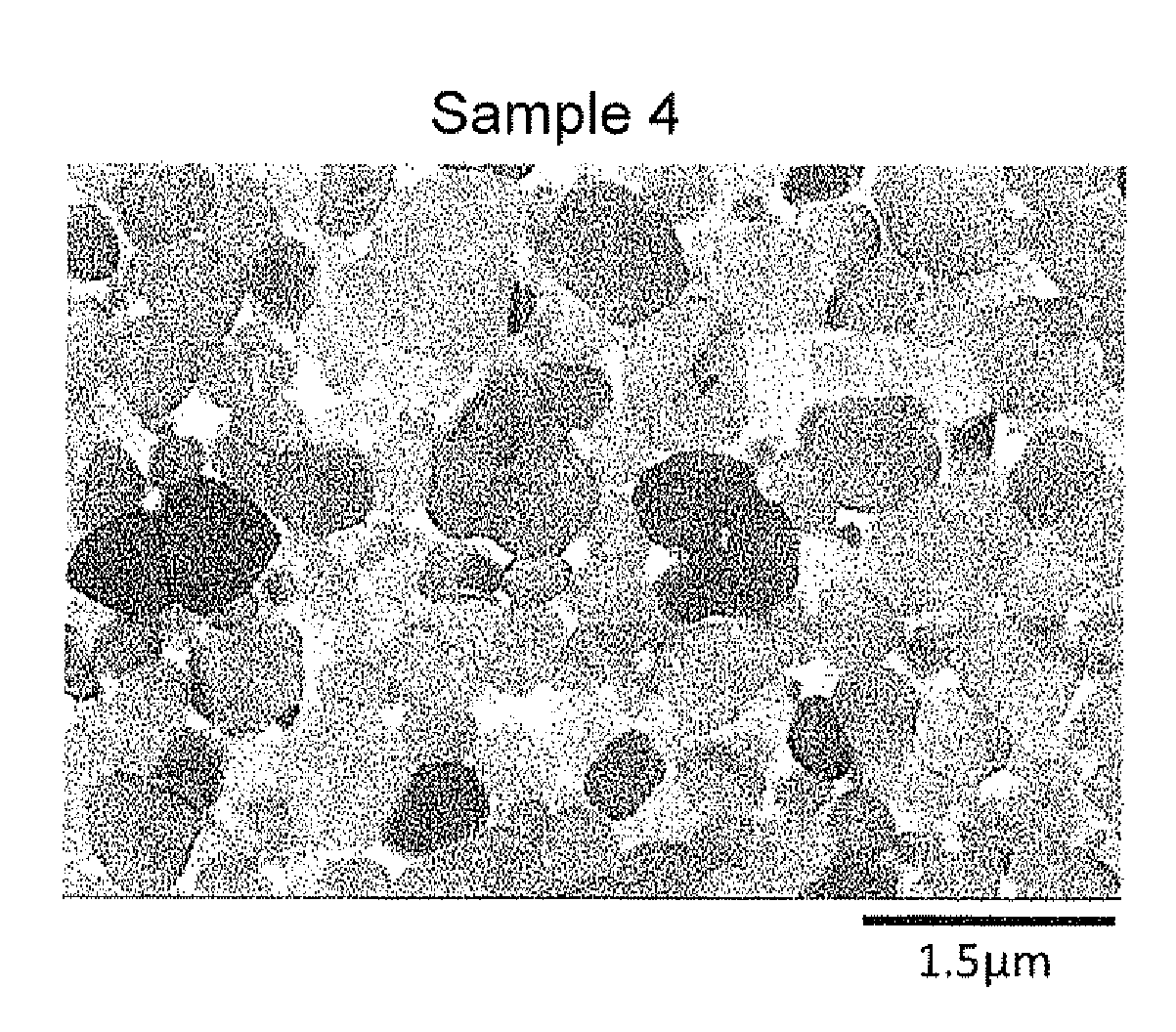
[0067]Firstly, as for materials of the main component, Fe2O3 powder, NiO powder, Cup powder and ZnO powder were prepared. As for materials of subcomponents, SiO2 powder and B2O3 powder were prepared. Note that an average particle size of material of SiO2 powder in sample 33 was 0.42 μm, and an average particle size of material of SiO2 powder in other samples except for sample 33 were 0.025 μm.

[0068]Next, prepared materials of main component and subcomponents were weighed so as to have the amounts shown in Tables 1 and 2, and then wet-mixed by a ball mill for 16 hrs so as to obtain a mixture of materials.

[0069]Next, the obtained mixture of materials was calcined in the air at 750° C. for 4 hrs so as to obtain a calcined material, and then the calcined material was wet-pulverized by a ball mill for 16 hrs and a pulverized material was obtained.

[0070]Next, after drying the pulverized material, 1.0 wt % of polyvinyl alcohol as a binder was added to 100 wt % of the pulverized material, a...

experiment 2

[0084]Except that compounds shown in Table 3 were used as subcomponents and contents thereof were set as amounts shown in the table 3, a toroidal core sample was produced as similar with the experiment 1 and characteristic evaluations as similar with the experiment 1 were performed. The results are shown in Table 3.

[0085]Note that, for sample 54, a glass composition where contents of the subcomponents with respect to 100 wt % of the main component becomes values shown in the Table 3 was used. Specifically, 2.5 wt % of the glass composition which includes 80 wt % of SiO2, 17 wt % of B2O3, 2.1 wt % of K2O was added to 100 wt % of the main component. Also, an average particle diameter of samples including K2O is preferably 0.2 to 1.3 μm.

TABLE 3AverageCompositioncrystalCharacteristicsMain componentSubcomponentparticleIdcSample(mol %)(wt %)diamterμi(10% off)μi × (Idc)2μ / μ25° C.No.Fe2O3 NiOCuOZnOSiO2B2O3K2OLi2ONa2OSnO2(μm)(0 mA)(mA)(A2)−25° C.85° C.4147.420.310.821.52.0——0.04——0.328048919...


PUM

PropertyMeasurementUnit
crystal particle sizeaaaaaaaaaa
melting pointaaaaaaaaaa

Abstract

A ferrite composition includes a main component having 46.0 to 49.8 mol % of an iron oxide in terms of Fe2O3, 5.0 to 14.0 mol % of a copper oxide in terms of CuO and 6.0 to 32.0 mol % of a zinc oxide in terms of ZnO, and a remainder of the main component is composed of a nickel oxide; and as subcomponents, with respect to 100 wt % of the main component, 0.5 to 6.0 wt % of a silicon oxide in terms of SiO2 and 0.01 to 2.0 wt % of a boron oxide in terms of B2O3. Further, as a subcomponent, 0.01 to 0.17 wt % of potassium oxide in terms of K2O or 0.3 to 2.0 wt % of tin oxide in terms of SnO2 may be included. According to the present invention, the ferrite composition having good initial permeability, good superposed direct current characteristic and comparatively good temperature characteristic of the initial permeability, and achieving low temperature firing; and an electronic component having the ferrite composition can be provided.

Description

BACKGROUND OF THE INVENTION[0001]1. Field of the Invention[0002]The present invention relates to a ferrite composition preferably used for electronic components such as an inductor element and the like, and an electronic component such as an inductor element to which said ferrite composition is applied.[0003]2. Description of the Related Art[0004]In recent years, reduction in size and weight for various kinds of electronic apparatuses such as a portable apparatus and the like are progressed rapidly. In order to respond this situation, demands of reduction in size and weight, and high performance for electronic components used for electric circuits of various kinds of electronic apparatuses are rapidly increased.[0005]In an electronic component such as an inductor element, a number of ferrite compositions having good magnetic characteristic are used as a magnetic material.[0006]Such material needs to show not only high magnetic permeability but also a small decrease in magnetic perme...

Claims


Application Information

Patent Timeline
Patent Type & Authority Applications(United States)
IPC IPC(8): H01F1/11
CPCB82Y30/00C01P2004/03C01G53/006C01P2002/52C01P2004/61C01P2006/42C04B35/265C04B2235/3201C04B2235/3203C04B2235/3279C04B2235/3281C04B2235/3284C04B2235/3293C04B2235/3409C04B2235/3418C04B2235/5436C04B2235/5454C04B2235/785C04B2235/786H01F1/344C01G49/0018C04B35/26H01F1/34
Inventor WADA, RYUICHIKAWADAHARA, SHOUTAKAHASHI, YUKIOMASAOKA, RAITAROUSUZUKI, TAKASHIMOMOI, HIROSHI
Owner TDK CORPARATION
Why Eureka
Try Eureka