Direct-Current Power Source Apparatus

a power source and direct-current technology, applied in the direction of emergency power supply arrangements, electric devices, machines/engines, etc., can solve the problems of secondary battery deformation, difficulty in fully utilizing lithium-ion capacitors in conventional direct-current power source apparatuses, and loss of original characteristics of lithium-ion capacitors, so as to prevent secondary battery degradation, reduce capacitance, and minimize electric power loss

Inactive Publication Date: 2011-09-22
SHIN KOBE ELECTRIC MASCH CO LTD
View PDF8 Cites 30 Cited by
  • Summary
  • Abstract
  • Description
  • Claims
  • Application Information

AI Technical Summary

Benefits of technology

[0008]Another object of the present invention is to provide a direct-current power source apparatus in which a lithium-ion capacitor unit is used as a main power source and a secondary battery is used as an auxiliary power source and in which a burden on the secondary battery is reduced to suppress degradation of the secondary battery and extend the life thereof.
[0035]The direct-current power source apparatus according to the present invention can be utilized as a power source for a transfer apparatus or an automated guided vehicle. Since the direct-current power source apparatus according to the present invention uses the lithium-ion capacitor unit as a main power source and the secondary battery as an auxiliary power source as discussed above, it is possible to reduce the size and the weight of the direct-current power source apparatus by reducing the capacity of the secondary battery, which makes the direct-current power source apparatus suitable for installation in a transfer apparatus.

Problems solved by technology

If the lithium-ion capacitor is overdischarged with its voltage falling below a lower-limit voltage inevitably determined by its characteristics, however, the lithium-ion capacitor may lose its original characteristics even if recharged.
Therefore, it is difficult to fully utilize the lithium-ion capacitor in the conventional direct-current power source apparatus.
Meanwhile, the secondary battery tends to be degraded by quick charging and discharging, overdischarging, and overcharging compared to the lithium-ion capacitor, and thus may be degraded if controlled by a conventional control method.

Method used


Image

  • Direct-Current Power Source Apparatus
  • Direct-Current Power Source Apparatus
  • Direct-Current Power Source Apparatus

Examples


first embodiment

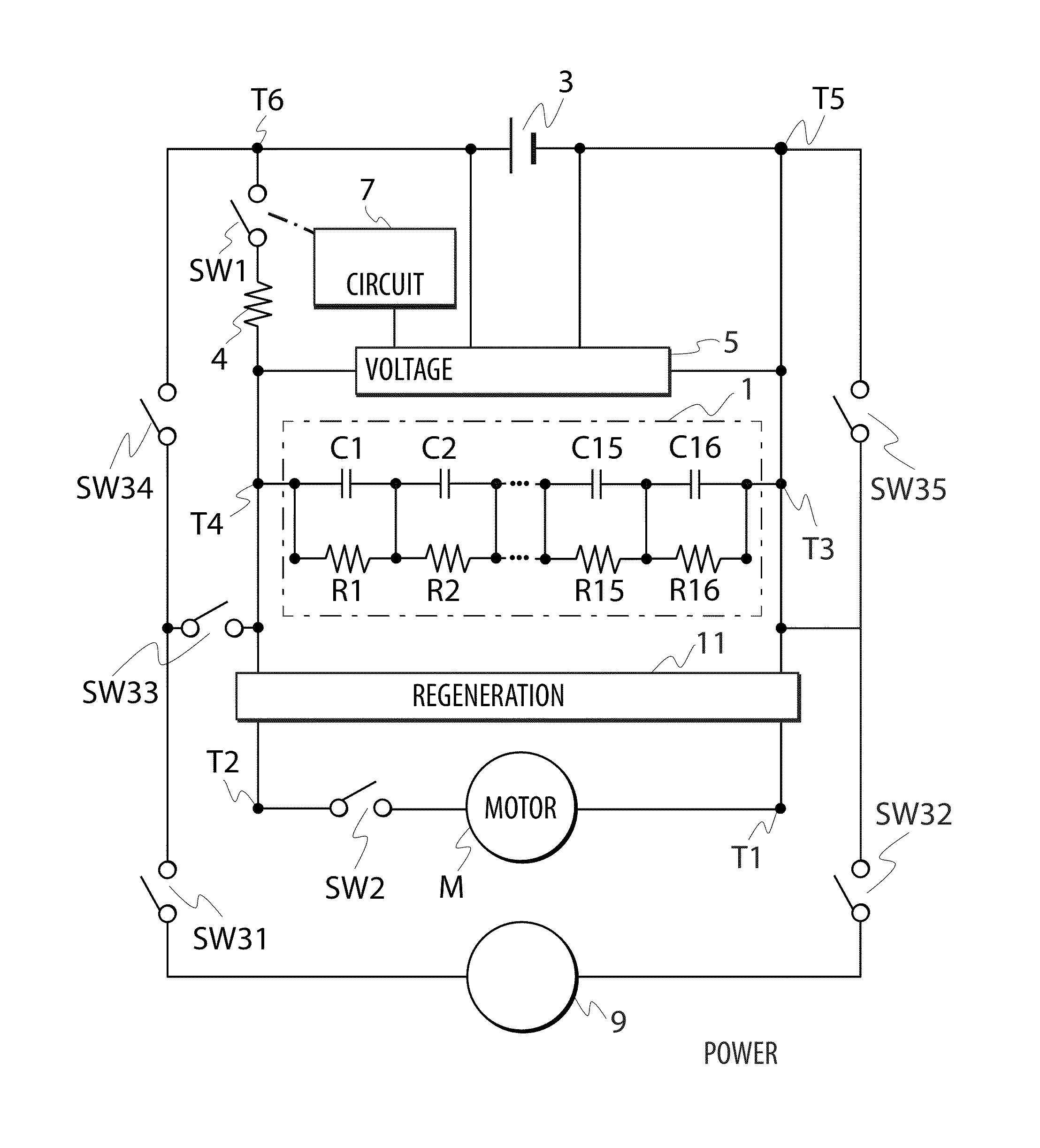
[0044]FIG. 1 is a circuit diagram showing the configuration of a direct-current power source apparatus according to a first embodiment of the present invention applied to an automated guided vehicle. The direct-current power source apparatus according to the embodiment includes a lithium-ion capacitor unit 1, a secondary battery 3 such as a lead-acid battery, a voltage detecting section 5, a control circuit 7, and a switching circuit SW1. The lithium-ion capacitor unit 1 and the secondary battery 3 are connected in parallel with a motor M serving as a load. A power switch SW2 that turns on during an operation is connected in series with the motor M. Specifically, one (input / output portion T3) of paired input / output portions (T3 and T4) of the lithium-ion capacitor unit 1, which is connected to one (input / output portion T1) of paired input / output portions T1 and T2 of the motor M, and one (input / output portion T5) of paired input / output portions (T5 and T6) of the secondary battery 3...

second embodiment

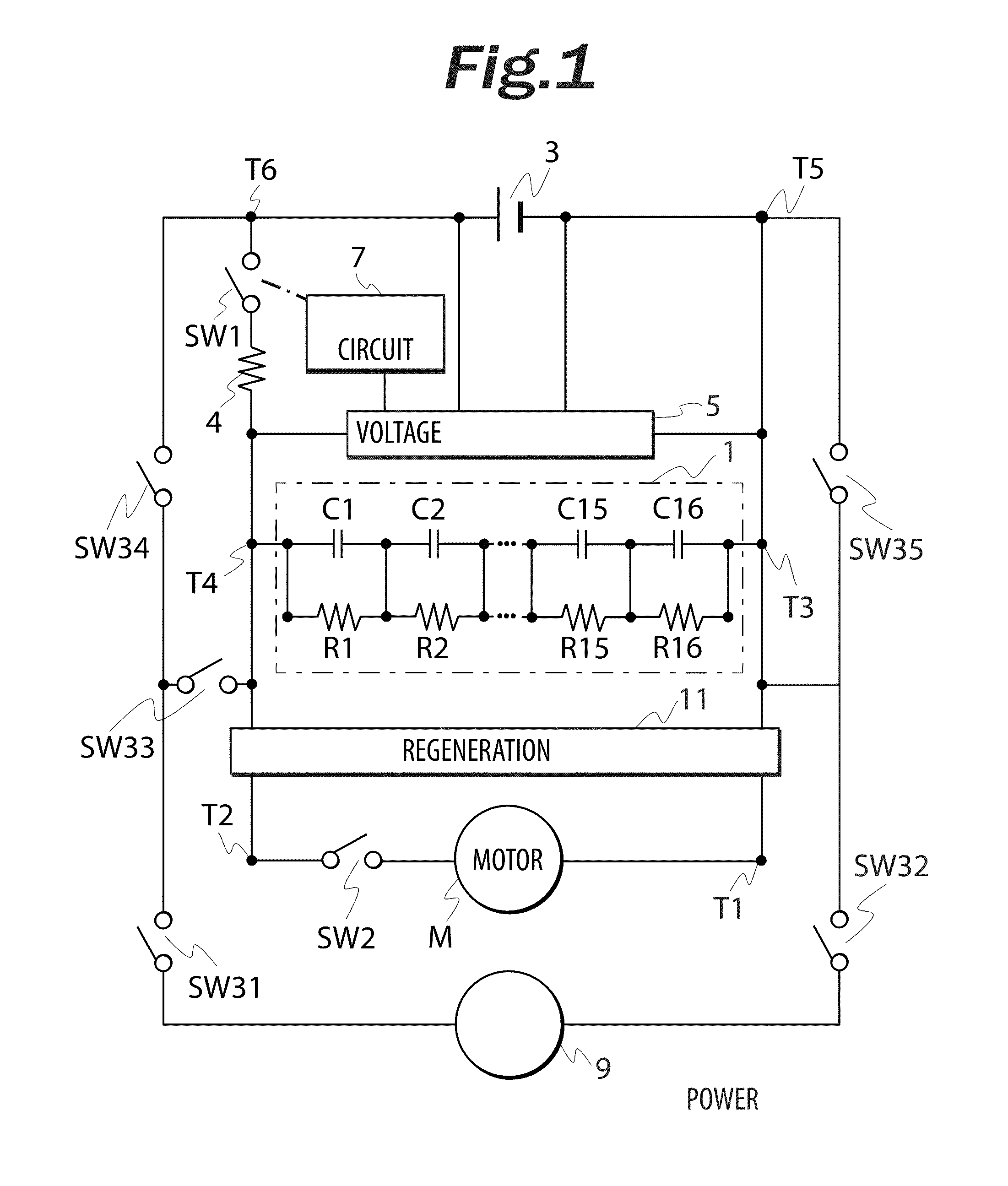
[0050]If a secondary battery, which can be charged in a short time, is used as the secondary battery in the direct-current power source apparatus, it is conceivable to contrive to charge the secondary battery along with charging a lithium-ion capacitor unit. FIG. 2 is a circuit diagram showing the configuration of a direct-current power source apparatus according to a second embodiment in which a diode D1 is disposed in parallel with the switching circuit SW1. In FIG. 2, component parts that are the same as those in the embodiment shown in FIG. 1 are denoted by reference numerals obtained by adding 100 to the reference numerals affixed to their counterparts in FIG. 1 to omit their descriptions. Specifically, the diode D1 has an anode connected to the input / output portion T4 of a lithium-ion capacitor unit 101 and a cathode connected to the input / output portion T6 as a positive terminal of a secondary battery 103. A current from the secondary battery 103 is blocked by the diode D1 wh...

third embodiment

[0051]In the embodiments described above, the switching circuit SW1 is used as the changeover circuit. However, the configuration of the changeover circuit which connects the secondary battery in parallel with the lithium-ion capacitor unit after the voltage of the lithium-ion capacitor unit has decreased is not limited to the switching circuit SW1. FIG. 3 is a circuit diagram showing the configuration of a direct-current power source apparatus according to a third embodiment of the present invention. The embodiment uses a unidirectional conductive device as the voltage detecting section and the changeover circuit. In FIG. 3, component parts that are the same as those in the embodiment shown in FIG. 1 are denoted by reference numerals obtained by adding 200 to the reference numerals affixed to their counterparts in FIG. 1 to omit their descriptions. In the embodiment, a Zener diode ZD1 is used as a unidirectional conductive device which serves as the voltage detecting section and th...


PUM


Abstract

A direct-current power source apparatus in which a lithium-ion capacitor unit is used as an electric storage system and which can fully utilize the lithium-ion capacitor unit and maintain the supply of electricity to a load is provided. An electric storage system includes a lithium-ion capacitor unit and a lead-acid battery connected in parallel with a load, and a voltage detecting section that detects the voltage of the lithium-ion capacitor unit. When the voltage detecting section detects that the voltage of the lithium-ion capacitor unit has reached a unit lower-limit voltage, a control circuit outputs a conduction signal for causing a switching circuit to get into a conductive state. When the switching circuit gets into a conductive state, the secondary battery supplies an electric power to a motor. At this time, the secondary battery charges the lithium-ion capacitor unit.

Description

BACKGROUND OF THE INVENTION[0001]1. Field of the Invention[0002]The present invention relates to a direct-current power source apparatus that supplies a load with a direct-current power discharged from an electric storage system.[0003]2. Description of the Related Art[0004]Conventional direct-current power source apparatuses use a capacitor or condenser with a relatively high capacitance to supply a direct-current power to a load such as a motor of an electric vehicle. See Japanese Utility Model Application Publication No. 03-104002 (JPU03-104002A) for example. Because the capacitor becomes unable to supply an electric power when charge falls short, conventional direct-current power source apparatuses additionally use a secondary battery to extend the time of use of a direct-current power. See Japanese Patent Application Publication No. 06-270695 (JP06-270695A), Japanese Patent Application Publication No. 2009-112122 (JP2009-112122A), Japanese Patent Application Publication No. 2004...

Claims


Application Information

Patent Timeline
Patent Type & Authority Applications(United States)
IPC IPC(8): H02J7/04H02J3/00H02J7/00B60L50/15
CPCH02J7/0024Y02T90/14H02J7/345H02J9/02B60L7/16B60L11/1809B60L11/187B60L11/005B60L11/12F02N11/0866F02N2011/0885Y02T10/7077Y02T10/7005Y02T10/705Y02T10/7022Y02T10/7016Y02T10/7011H02J7/047Y02T10/7072B60L50/40B60L50/15B60L53/00B60L58/24H02J7/007192Y02T10/70Y02T90/12H02J7/04B60L53/55B60L53/24B60L2210/10B60Y2200/91B60L3/0046
Inventor KANOH, MITSUYOSHIAMANO, MASAHIKOIIDA, YUKIOHAMA, YOSHIKIYAMADA, KEIZO
Owner SHIN KOBE ELECTRIC MASCH CO LTD
Why Eureka
Try Eureka