
Lens and lens array and manufacturing method thereof

a technology of lens array and lens, which is applied in the field of lenses and lens arrays, can solve the problems of deteriorating optical performance of the lens, large difference between the two, and coefficient of linear expansion of the metal making up the diaphragm, etc., and achieves the effect of deteriorating optical performance and easy lens manufacturing

Inactive Publication Date: 2011-09-22
FUJIFILM CORP
View PDF4 Cites 11 Cited by
  • Summary
  • Abstract
  • Description
  • Claims
  • Application Information

AI Technical Summary

Benefits of technology

[0010]An illustrative aspect of the invention is to prevent deterioration of optical performance, which would otherwise be caused by a temperature change, in connection with a lens integrally having a diaphragm and a lens array that is an aggregation of the lenses.
[0015]According to the configurations described above, both the lens and the diaphragm are formed from a heat resistant resin. A difference between an amount of thermal expansion of the lens and an amount of thermal expansion of the diaphragm caused by a temperature change incidental to reflow treatment, or the like, becomes smaller when compared with a case where either the lens or the diaphragm is formed from a resin and where the remaining is formed from metal, so that occurrence of distortion is inhibited. Therefore, deterioration of optical performance due to a temperature change occurring during reflow treatment, or the like, can be inhibited. The diaphragm is a coating layer that is made by applying a light blocking resin over a surface of a lens block and hence easy to manufacture the lens.

Problems solved by technology

However, a great difference usually exists between a coefficient of linear expansion of the metal making up the diaphragm and a coefficient of linear expansion of the resin making up the lens body.
For this reason, a difference occurs between the amount of thermal expansion of the diaphragm and the amount of thermal expansion of the lens body caused by a temperature change incidental to reflow treatment, or the like, which in turn causes distortion.
The distortion may induce deformation of the lens body and the diaphragm and separation of the lens body from the diaphragm, which deteriorates optical performance of the lens.
In addition, forming a deposited metal film used for making the diaphragm incurs a cost.

Method used


Image

  • Lens and lens array and manufacturing method thereof
  • Lens and lens array and manufacturing method thereof
  • Lens and lens array and manufacturing method thereof

Examples


Embodiment Construction

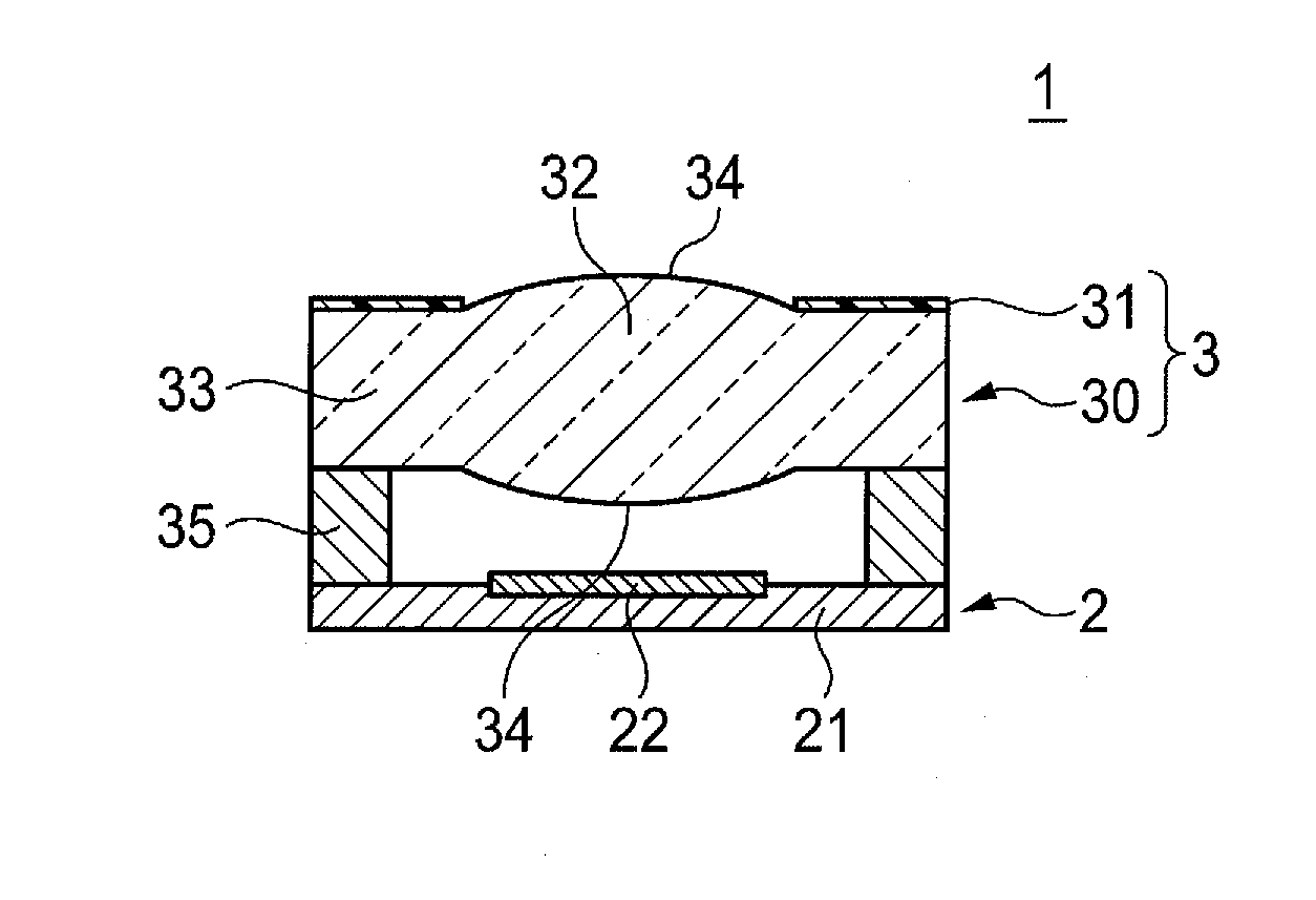
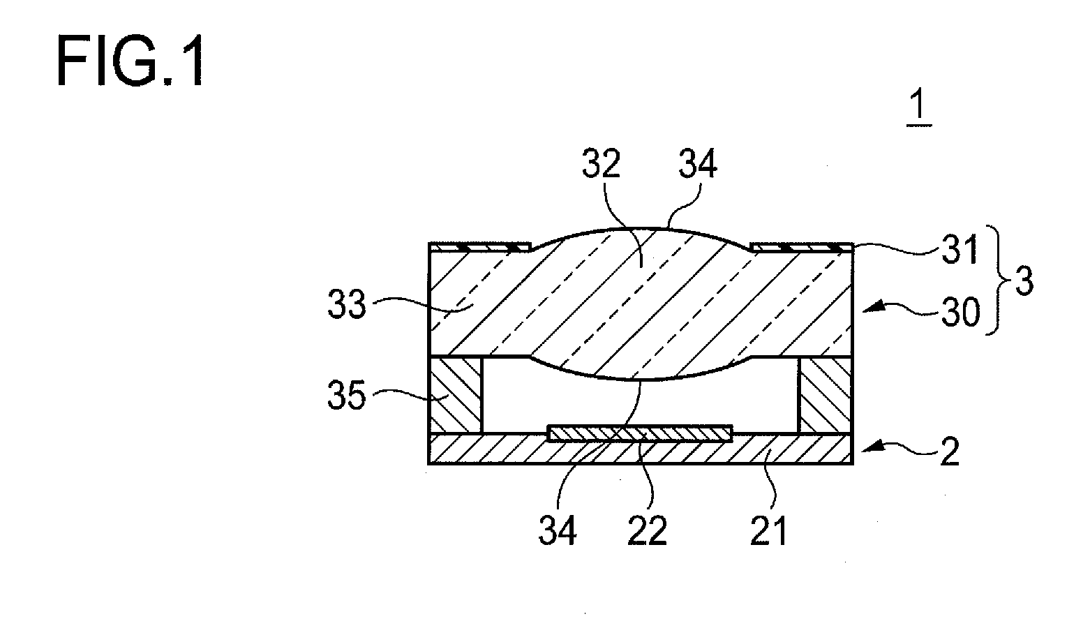
[0026]FIG. 1 shows an example imaging unit.

[0027]The imaging unit 1 shown in FIG. 1 has a sensor 2 including a solid state imaging element 22 and a lens 3.

[0028]The sensor 2 has a wafer piece 21. The wafer piece 21 is formed from; for instance, a semiconductor like silicon, and a solid state imaging element 22 is placed at a substantial center of the wafer piece 21. The solid state imaging element 22 is; for instance, a CCD image sensor and a CMOS image sensor. The wafer piece 21 is repeatedly subjected to processing pertaining to a well-known film formation step, a photolithography step, an etching step, an impurity doping step, and the like, whereby a light receiving region, electrodes, an insulation film, a line, and the like, are formed on the wafer piece 21.

[0029]The lens 3 has a lens body 30 and a diaphragm 31. The lens body 30 is made up of a lens block 32 and a flange block 33. The lens block 32 and the flange block 33 are integrally formed from a heat resistant, translucent...


PUM


Abstract

A lens is formed from a heat resistant resin and includes a diaphragm integrally provided on a surface of the lens. The diaphragm is a coating layer formed as a result of a heat resistant, light blocking resin being applied over the surface.

Description

CROSS-REFERENCE TO RELATED APPLICATIONS[0001]This application is based on and claims priority under 35 USC 119 from Japanese Patent Application No. 2010-065214 filed on Mar. 19, 2010; the entire contents of which are incorporated herein by reference.BACKGROUND[0002]1. Technical Field[0003]The present invention relates to a lens and a lens array and a manufacturing method thereof.[0004]2. Related Art[0005]An onboard imaging unit in an electronic device, such as a portable phone, generally has a solid state imaging element, such as a CCD (Charge Coupled Device) image sensor and a CMOS (Complementary Metal Oxide Semiconductor) image sensor, and an optical system that forms a subject image on the solid state imaging element. The optical system includes a built-in diaphragm for regulating brightness of an image.[0006]Reflow treatment is usually adopted for mounting an imaging unit on a circuit board of an electronic device. Reflow treatment refers to a technique for previously placing so...

Claims


Application Information

Patent Timeline
Patent Type & Authority Applications(United States)
IPC IPC(8): G02B1/10B05D5/06
CPCB29D11/00278
Inventor SAKAKI, TAKESHIFUJIWARA, TAKAYUKI
Owner FUJIFILM CORP
Learn More