Patterning process, resist composition, and acetal compound

Inactive Publication Date: 2011-09-29
SHIN ETSU CHEM CO LTD
39 Cites 65 Cited by

AI-Extracted Technical Summary

Problems solved by technology

If the acid in the exposed region evaporates during PEB and deposits on the unexposed region, the positive pattern following alkaline development suffers from such drawbacks as rounded top of its profile and film slimming.
Coverage of a photoresist film with a protective film is effect...

Method used

[0083]The above monomer is hydroxyadamantane methacrylate whose hydroxyl group is substituted by methylene acetal. By copolymerizing the monomer, there are obtained advantages such as excellent dissolution contrast during organic solvent development and control of acid diffusion. By virtue of improved dissolution contrast and controlled acid diffusion, a hole pattern after development is improved in dimensional uniformity.
[0125]If a polymer has a broad molecular weight distribution or dispersity (Mw/Mn), which indicates the presence of lower and higher molecular weight polymer fractions, there is a possibility that following exposure, foreign matter is left on the pattern or the pattern profile is exacerbated. The influences of molecular weight and dispersity become stronger as the pattern rule becomes finer. Therefore, the multi-component copolymer should preferably have a narrow dispersity (Mw/Mn) of 1.0 to 2.0, especially 1.0 to 1.5, in order to provide a resist composition suitable for micropatterning to a small feature size.
[0133]Onium salts such as sulfonium salts, iodonium salts and ammonium salts of sulfonic acids which are not fluorinated at α-position as described in US 2008153030 (JP-A 2008-158339) and similar onium salts of carboxylic acid may be used as the quencher. While an α-position fluorinated sulfonic acid, imide acid, and methide acid are necessary to deprotect the acid labile group of carboxylic acid ester, an α-position non-fluorinated sulfonic acid and a carboxylic acid are released by salt exchange with an onium salt which is not fluorinated at α-position. An α-position non-fluorinated sulfonic acid and a carboxylic acid function as a quencher because they do not induce deprotection reaction. In particular, since sulfonium salts and iodonium salts of an α-position non-fluorinated sulfonic acid and a carboxylic acid are photo-decomposable, those portions receiving a high light intensity are reduced in quenching capability and increased in the concentration of a α-position fluorinated sulfonic acid, imide acid, or methide acid. As a result, the exposed portions are improved in contrast. When a negative tone pattern is formed using an organic solvent, the improvement in the contrast of exposed portions leads to an improvement in the rectangularity of negative pattern. Onium salts including sulfonium salts, iodonium salts and ammonium salts of an α-position non-fluorinated sulfonic acid and a carboxylic acid are highly effective in controlling the diffusion of an α-position fluorinated sulfonic acid, imide acid and methide acid. This is because the onium salt resulting from salt exchange is less mobile due to a higher molecular weight. In the event that a hole pattern is formed by negative development, since acid is generated in many regions, it is very important to control the diffusion of acid from the exposed area to the unexposed area. The addition of onium salts including sulfonium salts, iodonium salts and ammonium salts of an α-position non-fluorinated sulfonic acid and a carboxylic acid as well as the carbamate compound capable of generating an amine compound under the action of acid is very important from the aspect of controlling acid diffusion.
[0135]Also a polymeric additive may be added for improving the water repellency on surface of a resist film as spin coated. This additive may be used in the topcoatless immersion lithography. These additives have a specific structure with a 1,1,1,3,3,3-hexafluoro-2-propanol residue and are described in JP-A 2007-297590 and JP-A 2008-111103. The water repellency improver to be added to the resist should be soluble in the organic solvent as the developer. The water repellency improver of specific structure with a 1,1,1,3,3,3-hexafluoro-2-propanol residue is well soluble in the developer. A polymer having an amino group or amine salt copolymerized as recurring units may serve as the water repellent additive and is effective for preventing evaporation of acid during PEB and avoiding any hole pattern opening failure after development. An appropriate amount of the water repellency improver is 0.1 to 20 parts, preferably 0.5 to 10 parts by weight per 100 parts by weight of the base resin.
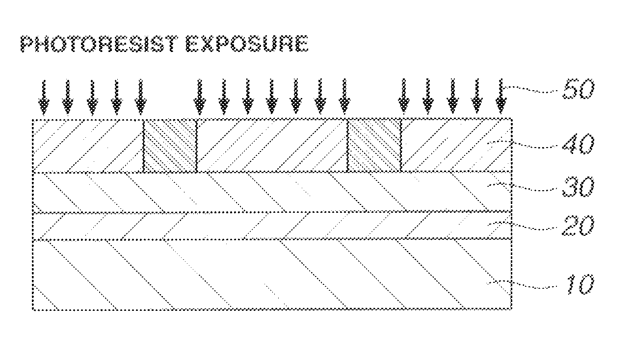
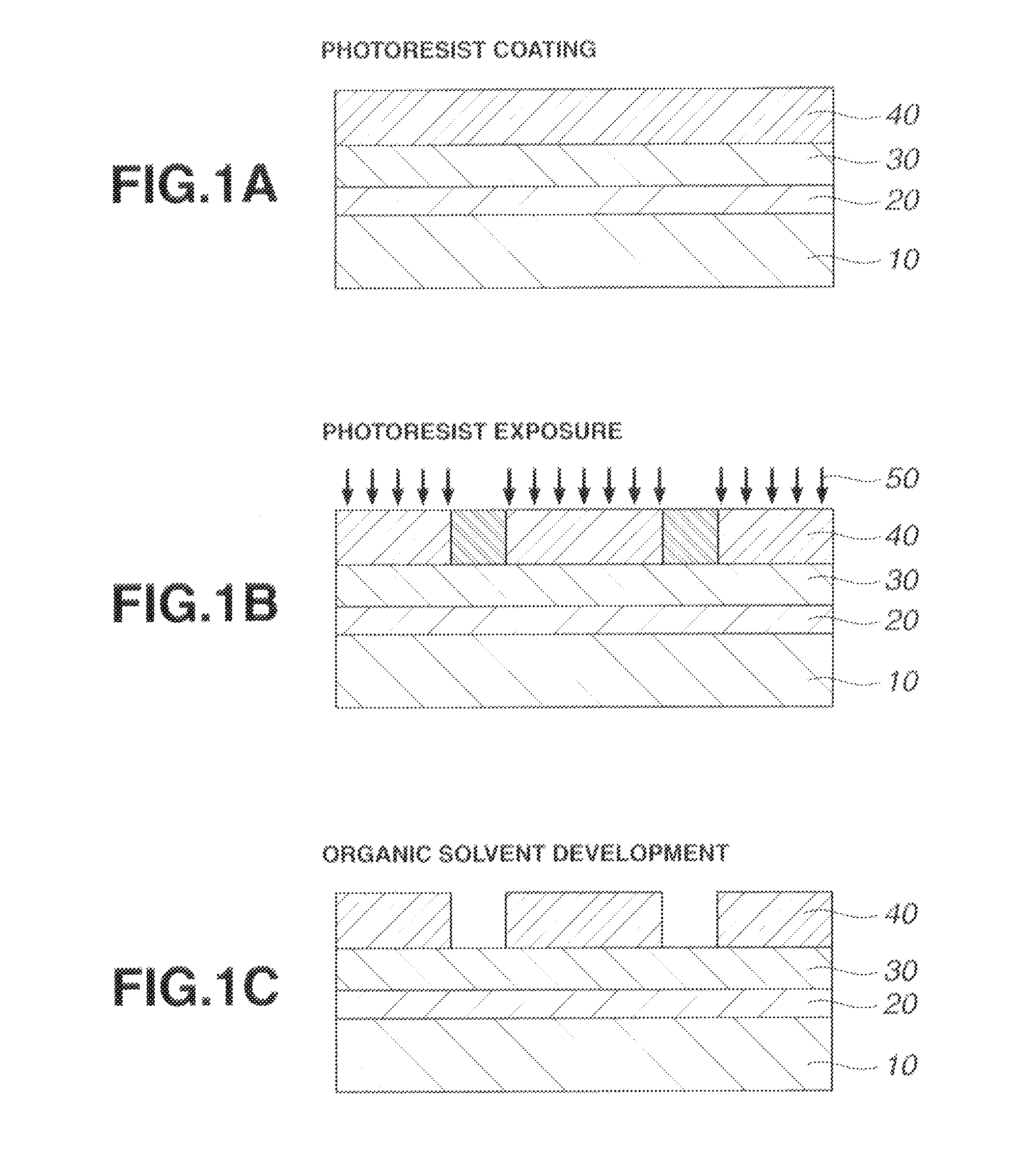
[0139]Next comes exposure depicted at 50 in FIG. 1B. For the exposure, preference is given to high-energy radiation having a wavelength of 140 to 250 nm and EUV having a wavelength of 13.5 nm, and especially ArF excimer laser radiation of 193 nm. The exposure may be done either in a dry atmosphere such as air or nitrogen stream or by immersion lithography in water. The ArF immersion lithography uses deionized water or liquids having a refractive index of at least 1 and highly transparent to the exposure wavelength such as alkanes as the immersion solvent. The immersion lithography involves prebaking a resist film and exposing the resist film to light through a projection lens, with water introduced between the resist film and the projection lens. Since this allows lenses to be designed to a NA of 1.0 or higher, formation of finer feature size patterns is possible. The immersion lithography is important for the ArF lithography to survive to the 45-nm node. In the case of immersion lithography, deionized water rinsing (or post-soaking) may be carried out after exposure for removing water droplets left on the resist film, or a protective film may be applied onto the resist film after pre-baking for preventing any leach-out from the resist film and improving water slip on the film surface.
[0142]After formation of the photoresist film, deionized water rinsing (or post-soaking) may be carried out for extracting the acid generator and the like from the film surface or washing away particles, or after exposure, rinsing (or post-soaking) may be carried out for removing water droplets left on the resist film. If the acid evaporating from the exposed region during PEB deposits on the unexposed region to deprotect the protective group on the surface of the unexposed region, there is a possibility that the surface edges of holes after development are bridged to close the holes. Particularly in the case of negative development, regions surrounding the holes receive light so that acid is generated therein. There is a possibility t...

Benefits of technology

[0046]In the process of image formation via positive/negative reversal by organic solvent development, a photoresist film comprising a polymer comprising recurring units having an acid labile group-substituted hydroxyl group and an acid generator is characterized by a high dissolution contrast between the unexp...

Abstract

A pattern is formed by applying a resist composition comprising a polymer comprising recurring units having an acid labile group-substituted hydroxyl group, an acid generator, and an organic solvent onto a substrate, prebaking the composition to form a resist film, exposing the resist film to high-energy radiation to define exposed and unexposed regions, baking, and developing the exposed film with an organic solvent developer to form a negative pattern wherein the unexposed region of film is dissolved and the exposed region of film is not dissolved.

Application Domain

Technology Topic

Image

  • Patterning process, resist composition, and acetal compound
  • Patterning process, resist composition, and acetal compound
  • Patterning process, resist composition, and acetal compound

Examples

  • Experimental program(4)

Example

Example
[0171]Examples of the invention are given below by way of illustration and not by way of limitation. The abbreviation “pbw” is parts by weight. Me stands for methyl. For all polymers, Mw and Mn are determined by GPC versus polystyrene standards using tetrahydrofuran solvent. For pattern profile observation, a top-down scanning electron microscope (TDSEM) S-9380 (Hitachi Hitechnologies, Ltd.) was used.

Example

Synthesis Example 1
[0172]Acetal compounds within the scope of the invention were synthesized in accordance with the formulation shown below.
Synthesis Example 1-1
Synthesis of Monomer 1
[0173]
[0174]In 200 ml of acetonitrile, 50.0 g of Starting Monomer 1 was mixed with 43.8 g of diisopropylethylamine and 0.05 g of 2,2′-methylenebis(6-t-butyl-p-cresol). To the mixture below 20° C., 40.4 g of chloromethyl neopentyl ether was added dropwise, followed by stirring at 40° C. for 8 hours. 300 ml of water was added to quench the reaction, followed by standard workup. Purification by distillation gave 59.9 g (yield 84%) of the end compound.
[0175]Boiling point: 102-104° C./10 Pa
[0176]IR (D-ATR): ν=2951, 2916, 2867, 1713, 1637, 1456, 1396, 1362, 1326, 1300, 1171, 1121, 1072, 1042, 1011, 982 cm−1
[0177]1H-NMR (600 MHz in DMSO-d6): δ=0.80 (9H, s), 1.47 (2H, t), 1.65-1.75 (4H, m), 1.80 (3H, s), 1.93-2.05 (4H, m), 2.11 (2H, s), 2.24-2.28 (2H, m), 3.12 (2H, s), 4.74 (2H, s), 5.58 (1H, m), 5.91 (1H, s) ppm

Example

Synthesis Example 1-2
Synthesis of Monomer 2
[0178]
[0179]Monomer 2 was prepared by the same procedure as Synthesis Example 1-1 except that Starting Monomer 2 was used instead of Starting Monomer 1. Yield 86%.
Synthesis Example 1-3
Synthesis of Monomer 3
[0180]
[0181]Monomer 3 was prepared by the same procedure as Synthesis Example 1-1 except that chloromethyl neohexyl ether was used instead of chloromethyl neopentyl ether. Yield 85%.
Synthesis Example 1-4
Synthesis of Monomer 4
[0182]Monomer 4 was prepared by the same procedure as Synthesis Example 1-1 except that chloromethyl (2-methyl-2-norbornyl)methyl ether was used instead of chloromethyl neopentyl ether. Yield 79%.
Synthesis Example 1-5
Synthesis of Monomer 5
[0183]Monomer 5 was prepared by the same procedure as Synthesis Example 1-1 except that chloromethyl (1-adamantyl)-methyl ether was used instead of chloromethyl neopentyl ether. Yield 82%.
Synthesis Example 1-6
Synthesis of Monomer 6
[0184]
[0185]Monomer 6 was prepared by the same procedure as Synthesis Example 1-1 except that Starting Monomer 3 was used instead of Starting Monomer 1. Yield 80%.
[0186]IR (D-ATR): ν=2953, 2868, 1717, 1637, 1480, 1453, 1396, 1363, 1321, 1294, 1242, 1164, 1140, 1080, 1041, 983 cm−1
[0187]1H-NMR (600 MHz in DMSO-d6): δ=0.85 (18H, s), 1.58-1.67 (4H, m), 1.76 (2H, d), 1.80 (2H, s), 1.87 (1H, d), 1.93 (2H, m), 2.06-2.13 (4H, m), 2.30-2.34 (1H, m), 3.12 (4H, s), 4.74 (4H, s), 5.58 (1H, m), 5.91 (1H, s) ppm
Synthesis Example 1-7
Synthesis of Monomer 7
[0188]Monomer 7 was prepared by the same procedure as Synthesis Example 1-1 except that Starting Monomer 3 was used instead of Starting Monomer 1, and chloromethyl (2-methyl-2-norbornyl)methyl ether was used instead of chloromethyl neopentyl ether. Yield 78%.
Synthesis Example 1-8
Synthesis of Monomer 8
[0189]Monomer 8 was prepared by the same procedure as Synthesis Example 1-1 except that Starting Monomer 3 was used instead of Starting Monomer 1, and chloromethyl (1-adamantyl)-methyl ether was used instead of chloromethyl neopentyl ether. Yield 74%.
Synthesis Example 1-9
Synthesis of Monomer 9
[0190]
[0191]Monomer 9 was prepared by the same procedure as
[0192]Synthesis Example 1-1 except that Starting Monomer 4 was used instead of Starting Monomer 1. Yield 76%.
Synthesis Example 1-10
Synthesis of Monomer 10
[0193]
[0194]Monomer 10 was prepared by the same procedure as Synthesis Example 1-1 except that Starting Monomer 5 was used instead of Starting Monomer 1. Yield 86%.
[0195]Boiling point: 122-125° C./10 Pa
[0196]IR (D-ATR): ν=2953, 2909, 2855, 1713, 1637, 1454, 1397, 1329, 1313, 1301, 1161, 1114, 1064, 1044, 1012, 970 cm−1
[0197]1H-NMR (600 MHz in DMSO-d6): δ=0.86 (9H, s), 1.38-1.49 (4H, m), 1.50-1.63 (2H, m), 1.80 (3H, s), 1.87 (2H, s), 1.96-2.08 (4H, m), 2.18 (2H, s), 3.10 (4H, d), 4.58 (2H, s), 5.56 (1H, m), 5.90 (1H, s) ppm
[0198]Monomers 1 to 10 obtained in Synthesis Example 1 have the structural formulae shown below.

PUM

PropertyMeasurementUnit
Size2.0E-9 ~ 3.0E-8m
Size2.0E-9 ~ 1.0E-7m
Wavelength193.0nm
tensileMPa
Particle sizePa
strength10

Description & Claims & Application Information

We can also present the details of the Description, Claims and Application information to help users get a comprehensive understanding of the technical details of the patent, such as background art, summary of invention, brief description of drawings, description of embodiments, and other original content. On the other hand, users can also determine the specific scope of protection of the technology through the list of claims; as well as understand the changes in the life cycle of the technology with the presentation of the patent timeline. Login to view more.

Similar technology patents

Resist composition and patterning process

ActiveUS20200218154A1High dissolution contrastWide depth of focusPhotomechanical exposure apparatusPhotosensitive material processingSolventChemical compound
Owner:SHIN ETSU CHEM IND CO LTD

Resist composition, pattern forming process, polymer, and monomer

ActiveUS20170184967A1High dissolution contrastImprove dof margin and mefOrganic chemistryRadiation applicationsRepeat unitMonomer
Owner:SHIN ETSU CHEM CO LTD

Classification and recommendation of technical efficacy words

  • High sensitivity
  • High dissolution contrast

System and method for optical coherence imaging

ActiveUS20060055936A1Sufficient signal to noise ratioHigh sensitivityInterferometersScattering properties measurementsPhysicsCoherent imaging
Owner:THE GENERAL HOSPITAL CORP

Catheter-free implantable needle biosensor

ActiveUS20080033269A1High sensitivitySimple stepSurgeryVaccination/ovulation diagnosticsNeedle electrodeElectricity
Owner:VIRTUE MEDICAL TECH (HUZHOU) CO LTD

Resist composition and patterning process

ActiveUS20200218154A1High dissolution contrastWide depth of focusPhotomechanical exposure apparatusPhotosensitive material processingSolventChemical compound
Owner:SHIN ETSU CHEM IND CO LTD

Resist composition, pattern forming process, polymer, and monomer

ActiveUS20170184967A1High dissolution contrastImprove dof margin and mefOrganic chemistryRadiation applicationsRepeat unitMonomer
Owner:SHIN ETSU CHEM CO LTD
Why Eureka
Try Eureka