Method for braking state monitoring and wind energy installation for carrying out the method

a technology of wind energy installation and braking state, which is applied in the direction of instruments, nuclear elements, machines/engines, etc., can solve the problems of maintenance effort, and achieve the effect of reducing computation complexity and determining the characteristic value of braking state more accurately

Inactive Publication Date: 2011-09-29
SENVION GMBH
View PDF8 Cites 3 Cited by
  • Summary
  • Abstract
  • Description
  • Claims
  • Application Information

AI Technical Summary

Benefits of technology

[0013]The measured values are preferably recorded using sensors which are provided in any case in the wind energy installation, independently of the monitoring of the brake. For example, these are sensors for the rotation speed or the time, which are required in the control system in order to set the wind energy installation to the correct operating point. The braking travel can be calculated from the measured values of the rotation speed and of the time. This embodiment does not require expensive sensors which are responsible only for monitoring of the brake.
[0016]Since no electricity can be produced during the waiting time, loss of yield resulting from the waiting time is, of course, undesirable. The invention now makes it possible to determine the brake cooling time individually after each braking process such that energy production can be resumed as quickly as possible.
[0017]One particularly advantageous method according to the invention provides for a wear characteristic value, which characterizes the brake wear, to be determined from the brake state characteristic value. It is therefore possible to determine the wear of the braking device and its progress without a sensor, which is susceptible to defects, in the brake linings. This avoids the costly sensor and the complex maintenance, while additionally improving the installation safety, because wear determination is safer, because the sensors are considerably more reliable.
[0019]Particularly when the intention is to also determine the wear from the brake state characteristic value, it may be advantageous to determine the brake state characteristic value more accurately, rather than on the basis of assumptions which are as simple as possible. For this purpose it is possible for the braking process to be subdivided into a multiplicity of short sections when determining the brake state characteristic value, and to determine the influence on the brake state characteristic value individually for each section. By way of example, the instantaneous rotation speed can be taken into account for each section. A correspondingly large number of measured values are preferably recorded during the braking process. It is therefore possible to take better account of the fact that the braking of a rotor is normally a non-linear process. This avoids the accumulation of errors resulting from inaccurate recording of the braking process over a multiplicity of braking processes leading to a major error in the brake state characteristic value.
[0020]In this case, it is particularly advantageous to record a measurement variable which represents an operating parameter of the wind energy installation that varies dynamically during the braking process, and to determine the brake state characteristic value from the change in the measurement variable during the braking process. In this case, dynamically means in particular parameters of the wind energy installation which do not vary linearly with the time, but follow more complex relationships which are predetermined, for example by the overall installation dynamics. Although the evaluation of dynamic measurement variables requires greater computation complexity, this also allows the brake state to be determined in more detail, however.

Problems solved by technology

Dedicated sensors must be provided, which in some cases operate in severe conditions and for this reason result in maintenance effort.

Method used


Image

  • Method for braking state monitoring and wind energy installation for carrying out the method
  • Method for braking state monitoring and wind energy installation for carrying out the method
  • Method for braking state monitoring and wind energy installation for carrying out the method

Examples


Embodiment Construction

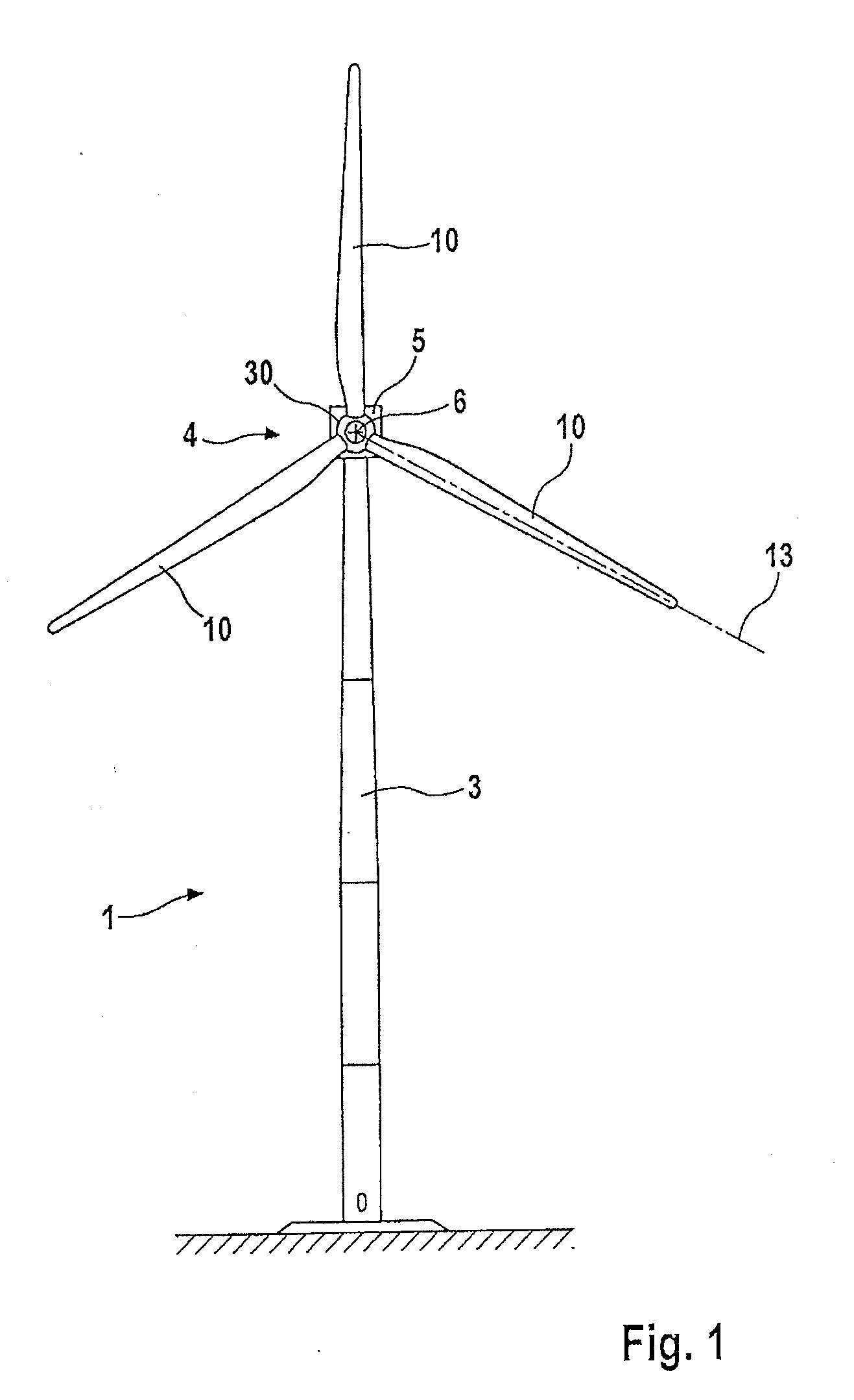
[0030]FIG. 1 shows a wind energy installation 1 with a tower 3, a machine housing which is mounted on the tower such that it can rotate about a vertical wind readjustment axis, a rotor 4 which is mounted such that it can rotate about a substantially horizontal axis 6 and has a rotor hub 30 on which three rotor blades 10 are arranged. The rotor blades are arranged on the rotor hub 30 such that the pitch angle is adjustable about a blade adjustment axis 13, which is shown by way of example for one rotor blade 10 in FIG. 1 and coincides substantially with the blade longitudinal axis.

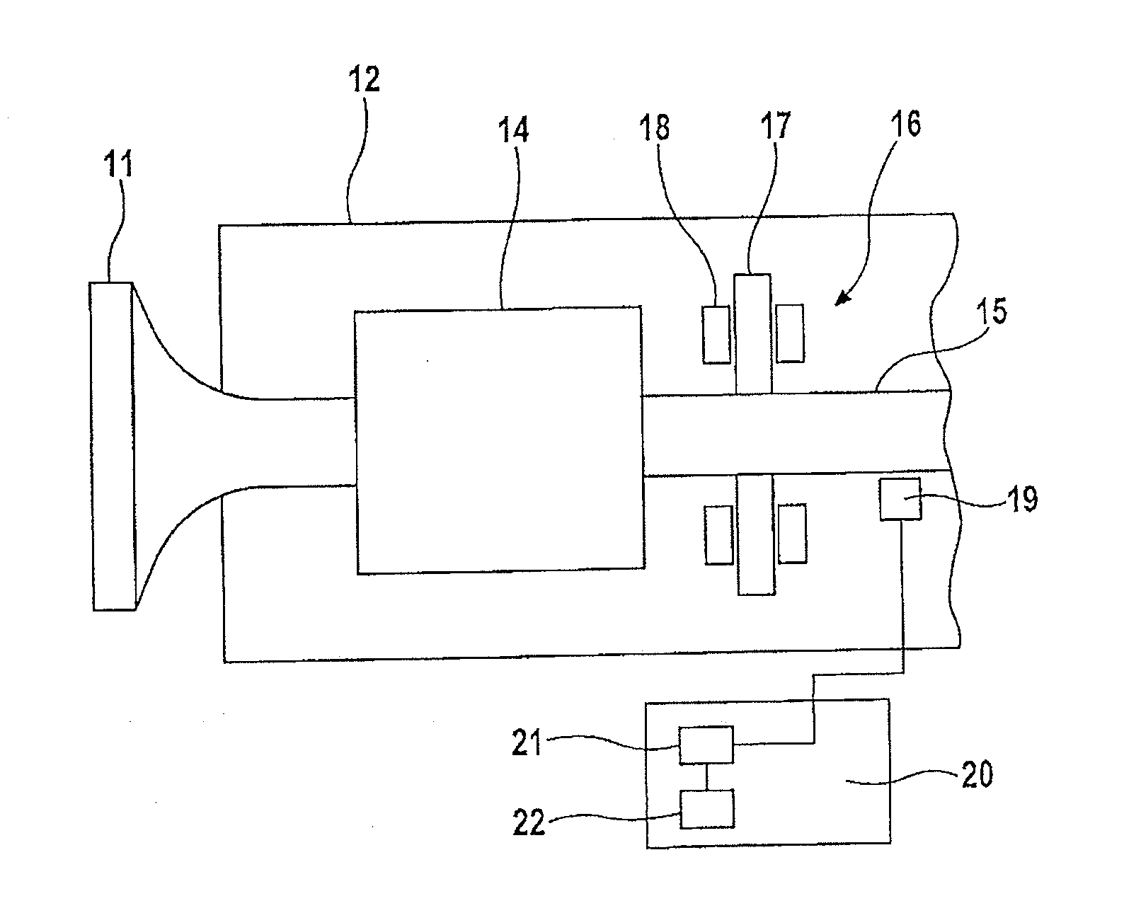
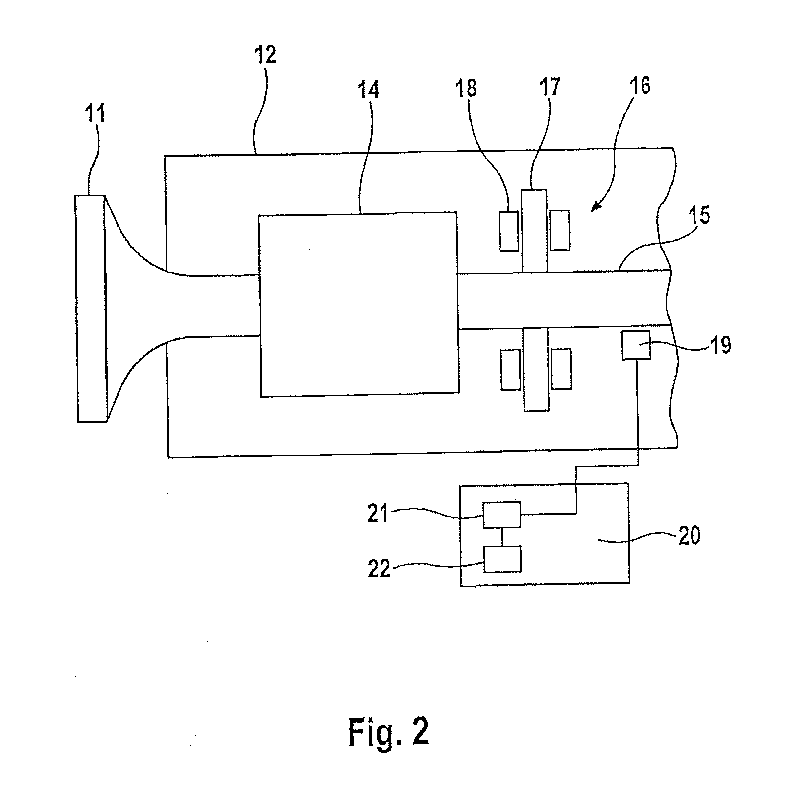
[0031]Some of the components of the wind energy installation from FIG. 1 are illustrated schematically in FIG. 2. A rotor shaft 11 extends into the machine housing 12, and opens in a transmission 14. The slow rotation of the rotor blades 11 is stepped up to a higher rotation speed in the transmission 14, and is transmitted to a generator shaft 15. The generator shaft 15 drives a generator, which is not illu...


PUM


Abstract

A method for determining the state of a braking apparatus of a wind energy installation can include obtaining data relating to load behavior of the braking apparatus, recording a measured value during a time period between a start of a braking process and an end of the braking process, and determining a brake state characteristic value based on the data and the measured value. A wind energy installation for performing the method can include a braking apparatus, a sensor, a control unit configured to instruct the sensor to record a measured value in a time period between a start of a braking process and an end of a braking process, a data memory configured to store data relating to load behavior of the braking apparatus, and a computation module configured to determine a brake state characteristic value based on the data and the measured value.

Description

REFERENCE TO RELATED APPLICATIONS[0001]This application claims the priority of German Patent Application No. 10 2010 012 957.7, filed Mar. 25, 2010, the contents of which are incorporated herein by reference.FIELD OF THE INVENTION[0002]The invention relates to a method for determining the state of a braking apparatus of a wind energy installation, and to a wind energy installation for carrying out the method.BACKGROUND OF THE INVENTION[0003]Modern wind energy installations generally have braking apparatuses, for example in order to brake the rotor in the event of malfunctions or for maintenance purposes, or for fixing the machine housing of the wind energy installation on the tower. In the first-mentioned situation, these are generally mechanical disk brakes, which act directly on the rotor rotation shaft, or indirectly via a transmission on the rotor. Mechanical brakes such as these have to be monitored in order to identify a malfunction in good time, and to preclude a safety risk....

Claims


Application Information

Patent Timeline
Patent Type & Authority Applications(United States)
IPC IPC(8): G06F15/00
CPCF03D7/0248Y02E10/723F05B2260/902F05B2260/80Y02E10/72
Inventor ALTEMARK, JENSBRUECKNER, MATTHIAS
Owner SENVION GMBH
Why Eureka
Try Eureka