Thermostatically controlled terminal box and photovoltaic power generation system utilizing the same
a photovoltaic power generation system and thermostatic control technology, applied in the field of photovoltaic power generation, can solve the problems of unimpeded solar panel voltage, damage to the system, and many currently used solar power systems that do not provide shutdown capability
- Summary
- Abstract
- Description
- Claims
- Application Information
AI Technical Summary
Benefits of technology
Problems solved by technology
Method used
Image
Examples
first embodiment
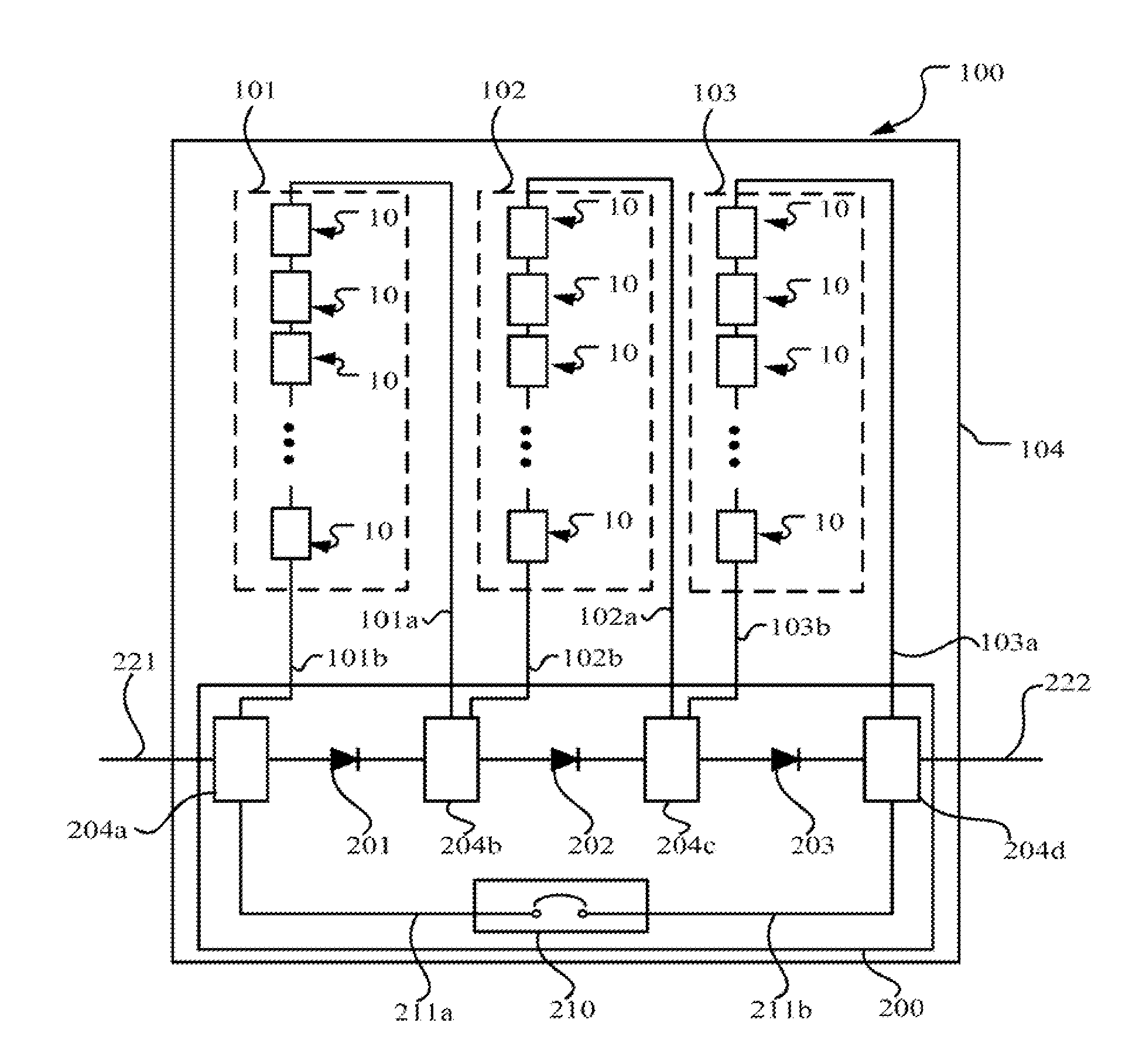
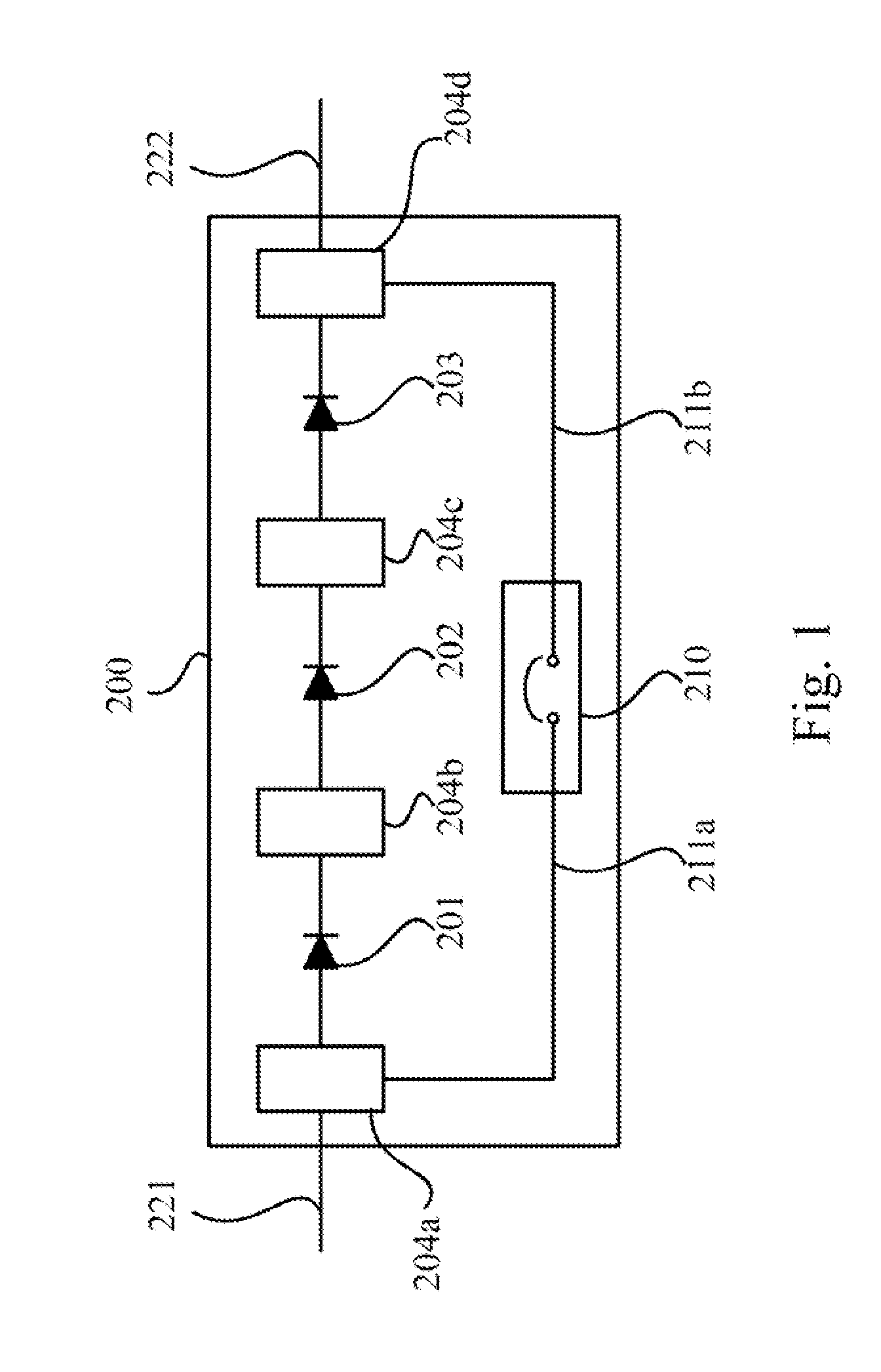
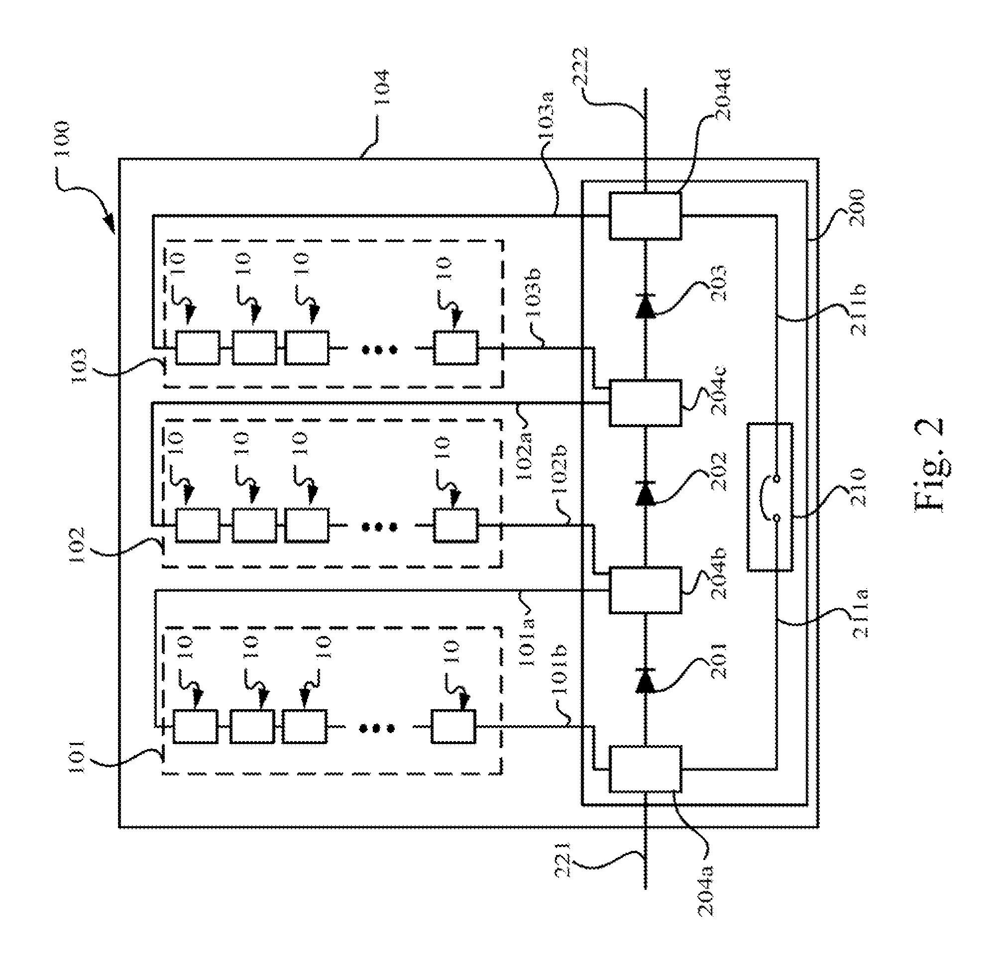
[0031]FIG. 4 is a cross section of the terminal box 200. Terminals 401 and 402 are a low voltage and a high voltage terminal of the terminal box, respectively. For example, the terminal 401 may electrically connect to or comprise the terminal 101b, 22a, component 204a, or a node portion thereof, and the terminal 402 may electrically connect to or comprise the terminal 103a, 22b, component 204d, or a joint portion thereof. An electrically conductive component 403, such as a metal plate, is fastened on housing 404 of the terminal box 200 with the terminal 401 by a fastening component 406. The electrically conductive component 403 has flexibility to change between a forced state and a released state. As shown in FIG. 6, the electrically conductive component 403 is retained in the forced state by a fuse 405, and has mechanical strength to return to the released state when the retention force of the fuse 405 is removed. As shown in FIG. 5, the electrically conductive component 403 in the...
second embodiment
[0033]With reference to FIG. 6, a switch device 210a is another example of a thermal switch 210 in a photovoltaic terminal box. A switch element 2101 of the switch device 210a may comprise a mechanical or solid state switch or relay with a control terminal 2101a connected to a controller 2102. The switch element 2101 responds to the signal received from the controller 2102 through the control terminal 2101a to electrically disconnect or connect terminals 2101b and 2101c, thus to transit the switch device 210a to the ON or OFF position. The switch element 2101 may be bistable in these two states and require manual operations to return from the OFF position to the ON position. Alternatively, the switch element 2101 once switched to the OFF position may be irreversible.
[0034]The controller 2102 may comprise an electric circuit in communication with a detection system 320 through a communication channel 301. The channel 301 may comprise a wired or a wireless communication channel. The d...
third embodiment
[0037]FIG. 7 shows switch device 210b of the thermal switch of a photovoltaic terminal box, differing from switch device 210a only in that the detection system 320 directly energizes and controls the switch element 2101 to switch from the ON position to the OFF position through the alarm signal respondent to a fire incident.
[0038]The switch element 2101 may connect to the detection system 320 through a power inverter which converts direct current (DC) signals generated by the photovoltaic power generation system to alternating current (AC) signals. The inverter receives and transfers the alarm signal from the detection system 320 to the switch element 2101. The inverter may perform signal analysis on the received alarm signal and convert the alarm signal by generating a version of the alarm signal conforming to a protocol between the inverter and the switch element 2101.
[0039]The terminal box 200 may include at least two of the exemplary embodiments of the thermal switches in the ho...
PUM
 Abstract
Description
Claims
Application Information
 - R&D
- Intellectual Property
- Life Sciences
- Materials
- Tech Scout
- Unparalleled Data Quality
- Higher Quality Content
- 60% Fewer Hallucinations
Browse by: Latest US Patents, China's latest patents, Technical Efficacy Thesaurus, Application Domain, Technology Topic, Popular Technical Reports.
© 2025 PatSnap. All rights reserved.Legal|Privacy policy|Modern Slavery Act Transparency Statement|Sitemap|About US| Contact US: help@patsnap.com


