Laser-based material processing apparatus and methods

a material processing and laser technology, applied in glass making apparatus, manufacturing tools, welding/soldering/cutting articles, etc., can solve the problems of significant drawbacks, and difficult to meet the requirements of various pcb designs, so as to improve processing throughput and/or quality, reduce processing costs, and reduce processing costs

Active Publication Date: 2011-10-06
IMRA AMERICA
View PDF5 Cites 95 Cited by
  • Summary
  • Abstract
  • Description
  • Claims
  • Application Information

AI Technical Summary

Benefits of technology

[0013]Because of at least the foregoing challenges and limitations, Applicants recognized a need exists not only to efficiently machine materials but also to avoid thermally or mechanically weakening the material, such adverse effects resulting from undesirable heat effects. Solutions which would eliminate expensive processing steps are highly desirable for certain implementations. Therefore, various embodiments of the systems and methods disclosed herein may be used for laser-based modification of composite target material of a workpiece while simultaneously achieving improvements in processing throughput and / or quality. Laser processing using embodiments of the disclosed system and methods may be an attractive alternative to conventional mechanical dicing methods, and may be utilized in combination with mechanical dicing (or other processing) for some applications.

Problems solved by technology

Therefore, challenges are apparent in fabrication of various PCB designs.
Physically separating, for example dicing, of a PCB comprising such composite material is not without challenges.
Conventional mechanical dicing has been the most common method, but with significant drawbacks.
When the material thickness becomes less than approximately 1000 μm, cutting with a mechanical saw may cause various problems such as chipping, fraying, tearing, and delamination.
Chemical processing bears high environmental cost and is considered, at the same time, non-green in many industries.

Method used


Image

  • Laser-based material processing apparatus and methods
  • Laser-based material processing apparatus and methods
  • Laser-based material processing apparatus and methods

Examples


examples and embodiments

Overview of Examples and Embodiments

[0117]As discussed above, Applicants have recognized that a need exists for laser-based processing to scribe, dice, cut, or other processing to remove material from a region of a composite material workpiece, so as to produce relatively narrow kerfs and relatively clean cuts with reduced thermal effects, while maintaining high throughput.

[0118]Embodiments of systems and methods disclosed herein are generally applicable for laser processing a workpiece, and particularly for micromachining applications. The workpiece may comprise a composite material. The workpiece may comprise a PCB. For example, various embodiments are applicable to cutting, dicing, scribing, and / or engraving composite materials to form features having a typical lateral dimension in a range from about 1 micron to about 100 microns and a depth from about a few microns to hundreds of microns. In some embodiments, the depth of the feature (e.g., a cut) may be equal to the thickness o...

embodiments and examples

VARIOUS EMBODIMENTS AND EXAMPLES

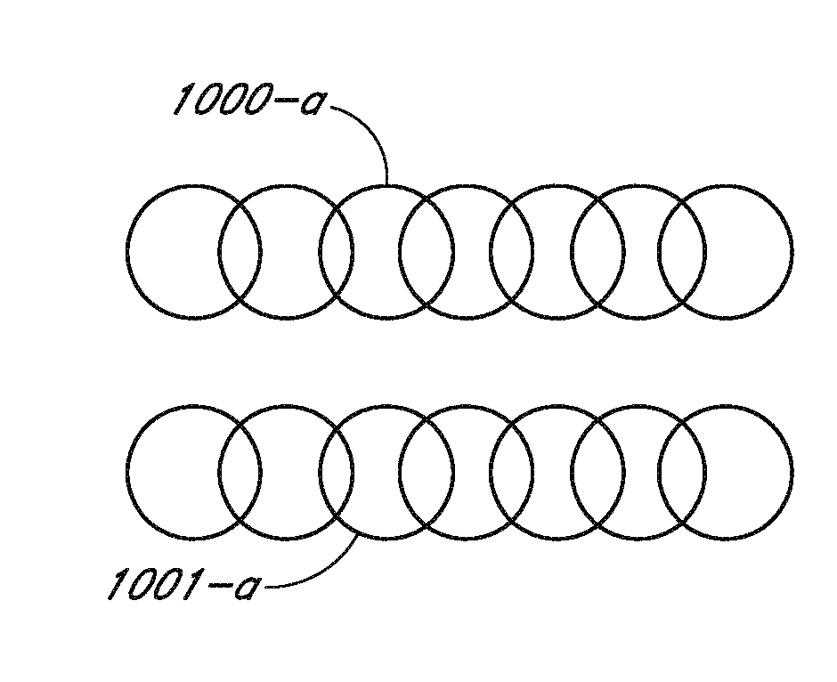
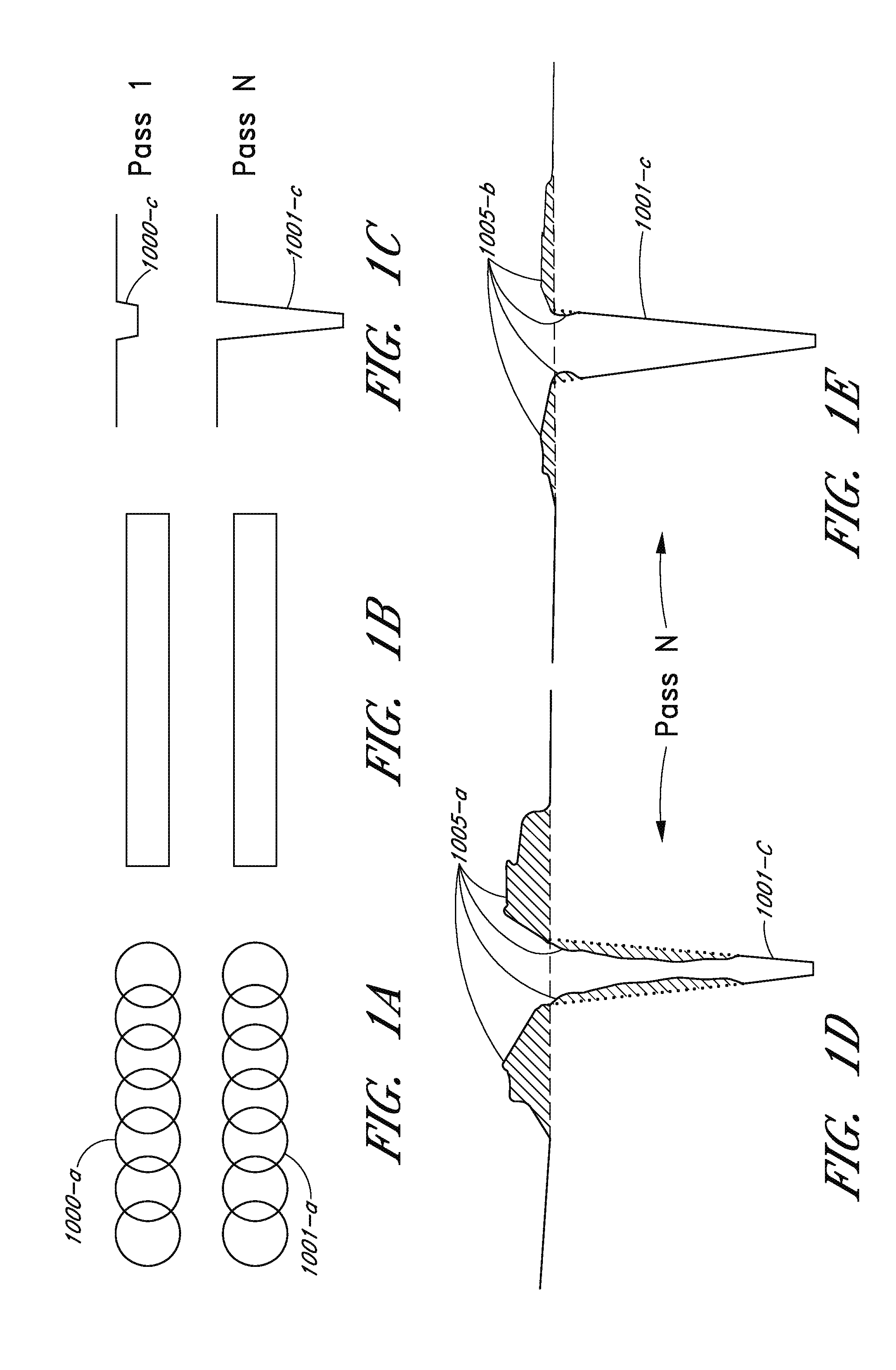
[0211]In another general aspect, a method of laser processing a composite material workpiece includes irradiating at least one material of the composite material workpiece with laser pulses having a pulse width. The laser pulses may be focused onto spots in the at least one material. The method includes moving the focused spots relative to the composite material at a relative speed. In some implementations, the workpiece comprises a patterned region and a composite material region. The patterned region may include electronic circuits comprising dielectric and / or metal materials. In some embodiments, the relative speed of the laser spot used for removal of at least a portion of the patterned region is substantially less than the relative speed used for removal of at least a portion of the composite material.

[0212]In some embodiments, an overlap between adjacent focused spots is substantially greater for irradiation of the patterned region than for irra...

example experimental

Results

[0225]Cutting Example with Ultrashort Pulses in Comparison with ns Pulses

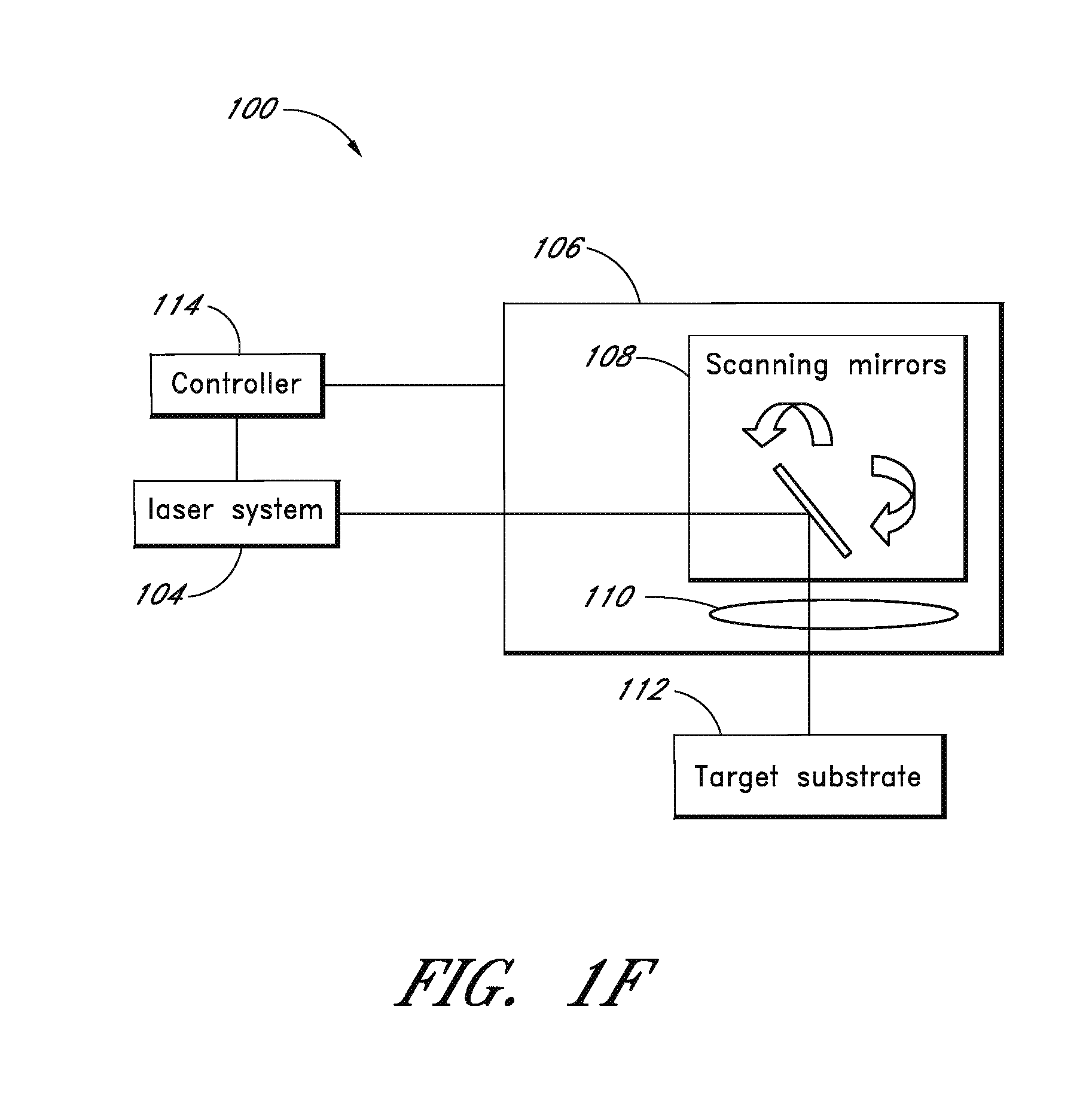
[0226]Experiments were carried out to compare cutting results obtained with ultrashort pulses and nanosecond pulses. The system configuration used was similar to the system schematically illustrated in FIG. 6A. In these experiments, the laser system 104 comprised a D-10K laser to provide ultrashort pulses and comprises a fiber-based ns laser unit to provide ns pulses; both lasers are made by IMRA America Inc. (Ann Arbor, Mich.).

[0227]The experimental arrangement is schematically illustrated in FIG. 6A. For the ultrashort pulse experiments, laser system 104 provided more than 10 μJ of available pulse energy, pulse widths in a range from about 500 fs to about 500 ps, and a repetition rate exceeding 100 kHz. The laser parameters of the experimental system were varied, although not necessarily all the parameters were independent of each other. For example, pulse energy influences the minimum achievable pulse...


PUM

PropertyMeasurementUnit
wavelengthaaaaaaaaaa

Abstract

Various embodiments may be used for laser-based modification of target material of a workpiece while advantageously achieving improvements in processing throughput and/or quality. Embodiments of a method of processing may include focusing and directing laser pulses to a region of the workpiece at a pulse width sufficiently short so that material is efficiently removed by nonlinear optical absorption from the region and a quantity of heat affected zone and thermal stress on the material within the region, proximate to the region, or both is reduced relative to a quantity obtainable using a laser with longer pulses. In at least one embodiment, an ultrashort pulse laser system may include at least one of a fiber amplifier or fiber laser. Various embodiments are suitable for at least one of dicing, cutting, scribing, and forming features on or within a composite material.

Description

CROSS REFERENCE TO RELATED APPLICATIONS[0001]This application claims the benefit under 35 U.S.C. §120 and 35 U.S.C. §365(c) as a continuation of International Application No. PCT / US2011 / 026501 designating the United States, with an international filing date of Feb. 28, 2011, entitled “LASER-BASED MATERIAL PROCESSING APPARATUS AND METHODS,” which claims the benefit under 35 U.S.C. §119(e) of U.S. Provisional Patent Application No. 61 / 319,220, filed Mar. 30, 2010, entitled “LASER-BASED MATERIAL PROCESSING APPARATUS AND METHODS,” the entire contents of each of the foregoing applications is hereby incorporated by reference herein and made a part of this specification.[0002]This application is related to U.S. patent application Ser. No. 12 / 641,256 filed Dec. 17, 2009 (hereinafter, the “'256 Application”), which published as U.S. Patent Application Publication No. 2010 / 0197116 on Aug. 5, 2010, which claims priority under 35 U.S.C. 120 and 35 U.S.C. 365(c) to co-pending International Appli...

Claims


Application Information

Patent Timeline
Patent Type & Authority Applications(United States)
IPC IPC(8): B23K26/36
CPCB23K26/00Y02P40/57B23K26/38B23K26/0624B23K2103/16B23K26/356B23K26/046C03B33/02
Inventor XU, JINGZHOUSOHN, JIN YOUNGCHO, GYU CHEONSHAH, LAWRENCE
Owner IMRA AMERICA
Why Eureka
Try Eureka