Substrate for a field emitter, and method to produce the substrate

a field emitter and substrate technology, applied in the manufacture of discharge tube main electrodes, electrode systems, electric discharge tubes/lamps, etc., can solve the problems of low mechanical stability and low current of computed tomography, and achieve long-term durability and high currents.

Inactive Publication Date: 2011-10-20
SIEMENS AG
View PDF3 Cites 12 Cited by
  • Summary
  • Abstract
  • Description
  • Claims
  • Application Information

AI Technical Summary

Benefits of technology

[0005]An object of the present invention is to provide carbon-based structures with long edges and many peaks in order to enable higher currents and a self-stabilizing, long-term durability (stability) of field electron emitters for use in high vacuum for applications in, among other things, computed tomography.

Problems solved by technology

The disadvantage of the known field emitters of the type used in computed tomography is the low currents and low mechanical stability associated therewith.

Method used


Image

  • Substrate for a field emitter, and method to produce the substrate
  • Substrate for a field emitter, and method to produce the substrate
  • Substrate for a field emitter, and method to produce the substrate

Examples


Embodiment Construction

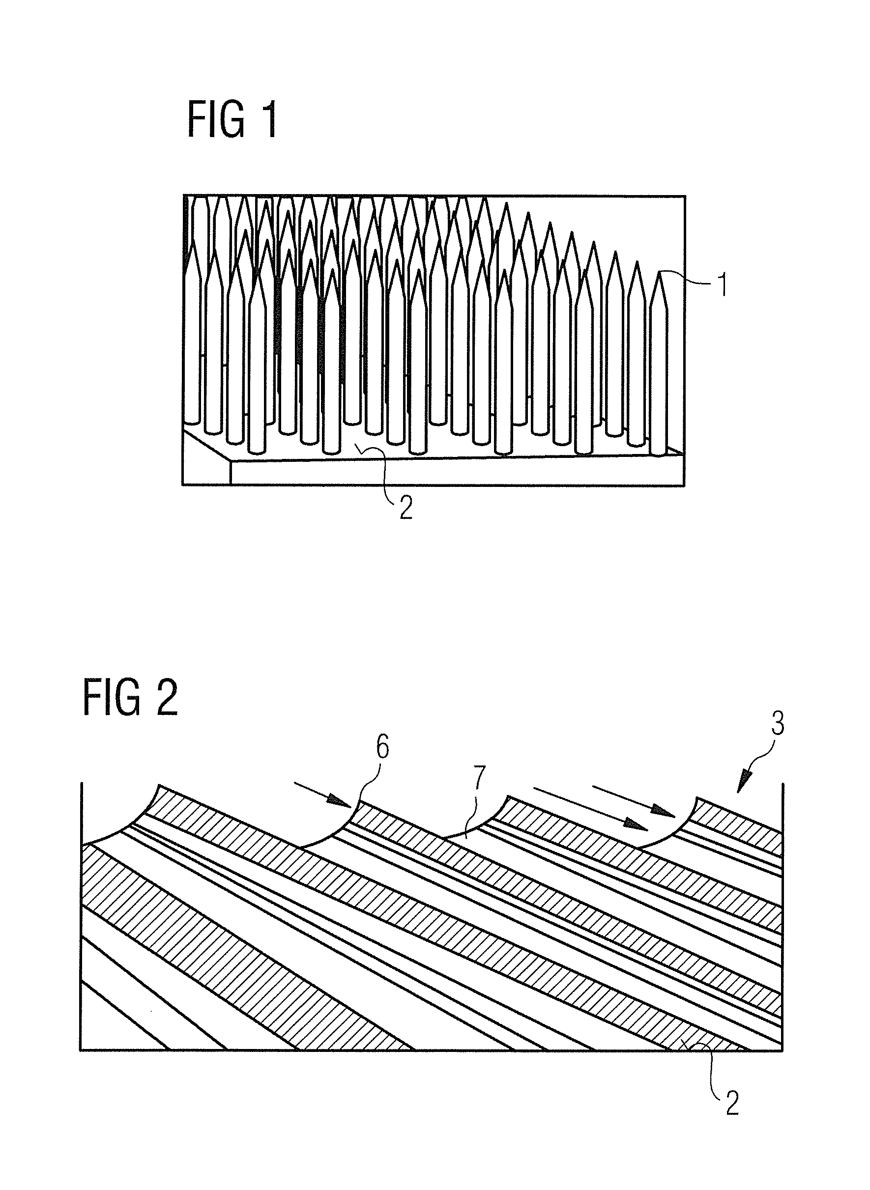
[0028]FIG. 1 schematically shows a CNT forest on a conductive surface. The peaks 1 of the CNTs are apparent.

[0029]The advantage of the CNTs is that high emitter currents can be emitted at numerous CNT point sources. The bonding of the pure CNTs to metal surfaces can be supported by conductive adhesives. Pure multiple graphite binder layers combine the advantages of high emitter currents, mechanical stability and negligible components of low molecular weight and therefore are particularly well suited for high vacuum applications.

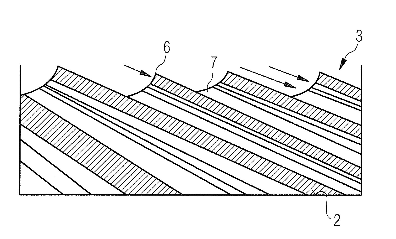
[0030]FIG. 2 shows the graphite layer structure 3, wherein the graphite layer is arranged like an unfolded paper or film on the substrate surface 2. The graphite layer structure shows high emitter currents at the long emitter edges 6 or graphene edges. The valleys 7—in which the peaks of the CNTs according to the invention can be arranged according to one embodiment of the invention—lie between the emitter edges 6.

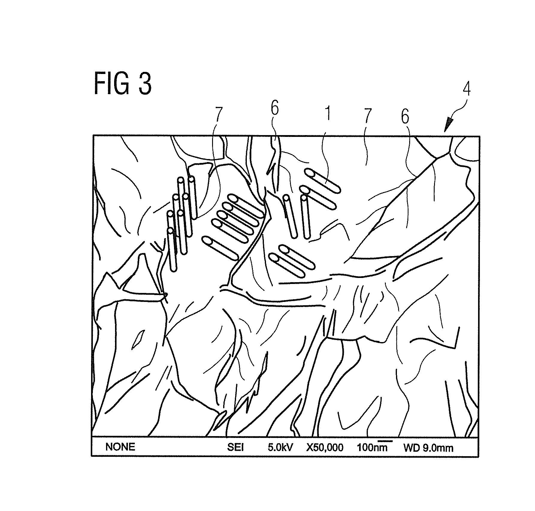
[0031]FIG. 3 shows the morphology of a graphi...


PUM

PropertyMeasurementUnit
temperaturesaaaaaaaaaa
temperatureaaaaaaaaaa
electrically conductiveaaaaaaaaaa

Abstract

A substrate for a field emitter suitable for use in computed tomography has a coating with carbon hybrid structures based on the allotropes graphite, graphene and nanotubes. The field emitters are based on graphite layer structures. A substrate for field emitters is achieved for the first time that uses “graphite combs” protruding and aligned essentially perpendicular to the substrate as well as hybrid materials from these combs with CNTs supported between them on a conductive substrate.

Description

BACKGROUND OF THE INVENTION[0001]1. Field of the Invention[0002]The invention concerns a substrate for a field emitter of the type suitable for use in computed tomography, as well as a method to produce the substrate and use of the substrate, in particular in computer tomography.[0003]2. Description of the Prior Art[0004]The disadvantage of the known field emitters of the type used in computed tomography is the low currents and low mechanical stability associated therewith.SUMMARY OF THE INVENTION[0005]An object of the present invention is to provide carbon-based structures with long edges and many peaks in order to enable higher currents and a self-stabilizing, long-term durability (stability) of field electron emitters for use in high vacuum for applications in, among other things, computed tomography.[0006]A general basis of the invention is the insight that aligned CNTs and unfolded carbon graphene or, multislice graphite (<10 graphene layers) (thus graphite structures with s...

Claims


Application Information

Patent Timeline
Patent Type & Authority Applications(United States)
IPC IPC(8): H01J1/02B05D5/12B82Y30/00
CPCC01B31/0423H01J1/304H01J2235/062H01J35/065H01J2201/30469H01J9/025C01B32/225
Inventor ZEININGER, HEINRICH
Owner SIEMENS AG
Why Eureka
Try Eureka