
Thermal conductive sheet

Inactive Publication Date: 2011-10-27
NITTO DENKO CORP
View PDF5 Cites 11 Cited by
  • Summary
  • Abstract
  • Description
  • Claims
  • Application Information

AI Technical Summary

Benefits of technology

[0010]An object of the present invention is to provide a thermal conductive sheet that is excellent in thermal conductivity in the plane direction, and also excellent in resistance to dielectric breakdown.
[0012]The thermal conductive sheet of the present invention is excellent in thermal conductivity in a plane direction that is perpendicular to the thickness direction, and also excellent in resistance to dielectric breakdown.
[0013]Therefore, by covering electronic components used in power electronics and / or a mounting substrate on which the electronic components are mounted with the thermal conductive sheet of the present invention, dielectric breakdown of the thermal conductive sheet can be prevented, and at the same time, the thermal conductive sheet allows the heat from the electronic components and / or the mounting substrate to be dissipated along the plane direction.

Problems solved by technology

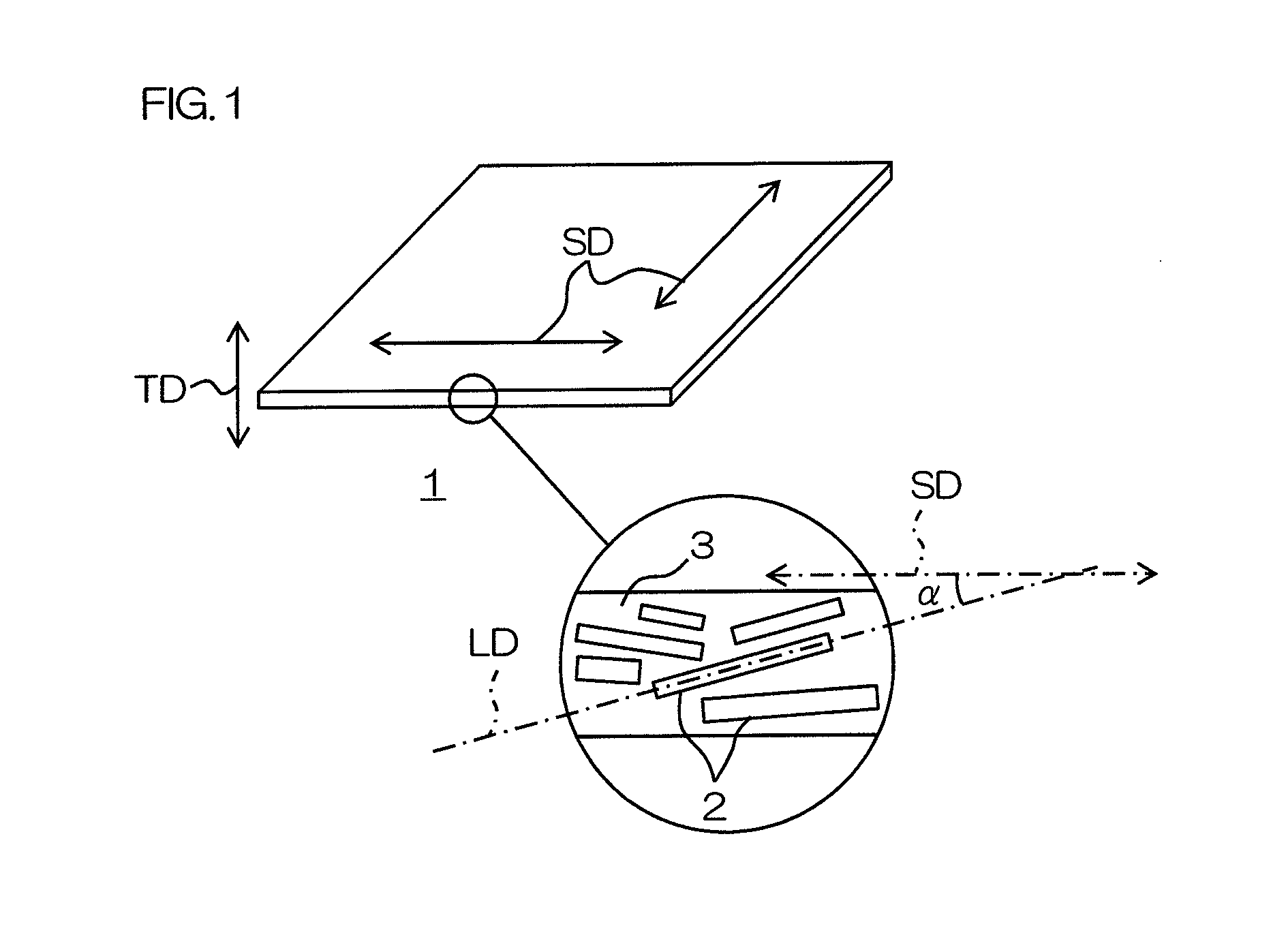
In such a case, the thermal conductive sheet of Japanese Unexamined Patent Publication No. 2008-280496 is disadvantageous in that the major axis direction of the boron nitride powder is perpendicular to (crossing) the plane direction, and therefore the thermal conductivity in the plane direction is insufficient.

Method used


Image

  • Thermal conductive sheet
  • Thermal conductive sheet
  • Thermal conductive sheet

Examples


example 1

[0159]The components described below were blended, stirred, and allowed to stand at room temperature (23° C.) for one night, thereby allowing methyl ethyl ketone (dispersion medium for the curing agent) to volatilize and preparing a semi-solid mixture. The details of the components are as follows: 13.42 g of PT-110 (trade name, plate-like boron nitride particles, average particle size (light scattering method) 45 μm, manufactured by Momentive Performance Materials Inc.), 1.0 g of jER®828 (trade name, bisphenol A epoxy resin, first epoxy resin, liquid, epoxy equivalent 184 to 194 g / eqiv., softening temperature (ring and ball method) below 25° C., melt viscosity (80° C.) 70 mPa·s, manufactured by Japan Epoxy Resins Co., Ltd.), 2.0 g of EPPN-501HY (trade name, triphenylmethane epoxy resin, second epoxy resin, solid, epoxy equivalent 163 to 175 g / eqiv., softening temperature (ring and ball method) 57 to 63° C., manufactured by NIPPON KAYAKU Co., Ltd), and 3 g (solid content 0.15 g) (5 m...

examples 2 to 9 and 11 to 16

[0166]Thermal conductive sheets were obtained in the same manner as in Example 1 in conformity with the mixing formulation and production conditions shown in Table 1 to Table 3.

example 10

[0167]A mixture was prepared by blending and stirring components (boron nitride particles and polyethylene) in accordance with the mixing formulation of Table 2. That is, in the stirring of the components, the mixture was heated to 130° C., and polyethylene was melted.

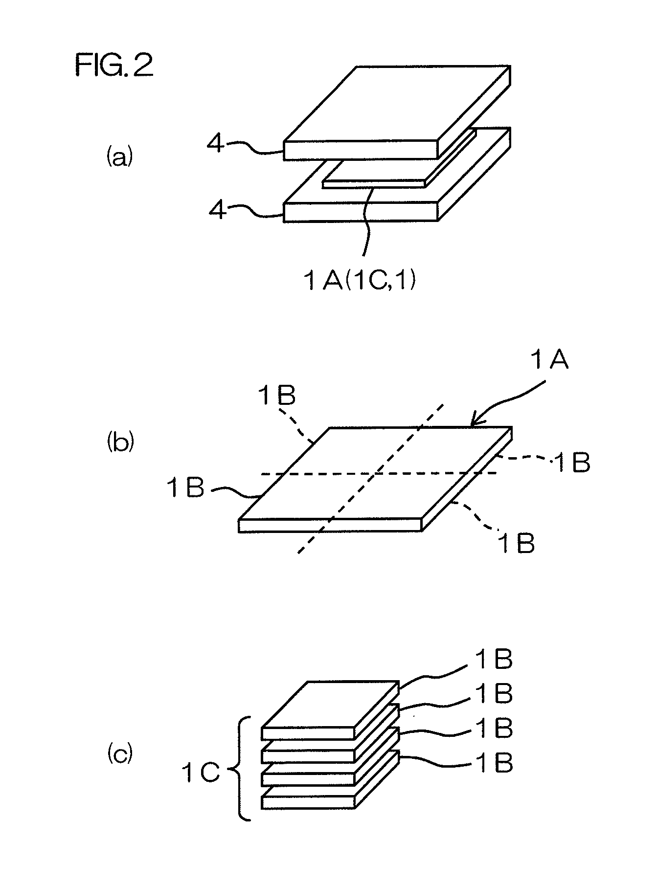
[0168]Then, the obtained mixture was sandwiched by two silicone-treated releasing films, and then these were hot-pressed with a vacuum hot-press at 120° C. under an atmosphere (vacuum atmosphere) of 10 Pa with a load of 1 ton (4 MPa) for 2 minutes. A pressed sheet having a thickness of 0.3 mm was thus obtained (ref: FIG. 2 (a)).

[0169]Thereafter, the obtained pressed sheet was cut so as to be divided into a plurality of pieces when projected in the thickness direction of the pressed sheet. Divided sheets were thus obtained (ref: FIG. 2 (b)). Next, the divided sheets were laminated in the thickness direction. A laminated sheet was thus obtained (ref: FIG. 2 (c)).

[0170]Then, the obtained laminated sheet was hot-pressed un...


PUM

PropertyMeasurementUnit
Thermal conductivityaaaaaaaaaa
Electric field strengthaaaaaaaaaa
Temperatureaaaaaaaaaa

Abstract

A thermal conductive sheet contains a plate-like boron nitride particle, wherein the thermal conductivity in a direction perpendicular to the thickness direction of the thermal conductive sheet is 4 W / m·K or more. The breakdown voltage of the thermal conductive sheet as measured in conformity with JIS C 2110 (2010) is 10 kV / mm or more.

Description

CROSS-REFERENCE TO RELATED APPLICATION[0001]The present application claims priority from Japanese Patent Application No. 2010-018256 filed on Jan. 29, 2010; Japanese Patent Application No. 2010-090908 filed on Apr. 9, 2010; and Japanese Patent Application No. 2010-161847 filed on Jul. 16, 2010, the contents of which are hereby incorporated by reference into this application.BACKGROUND OF THE INVENTION[0002]1. Field of the Invention[0003]The present invention relates to a thermal conductive sheet, to be specific, to a thermal conductive sheet for use in power electronics technology.[0004]2. Description of Related Art[0005]In recent years, power electronics technology, in which semiconductor elements are used to convert and control electric power, is applied in hybrid devices, high-brightness LED devices, and electromagnetic induction heating devices. In power electronics technology, a high current is converted to, for example, heat, and therefore materials that are disposed near the ...

Claims


Application Information

Patent Timeline
IPC IPC(8): F28F7/00
CPCC08L23/06C08L63/00C08L101/12B32B37/10B32B2307/202B32B2457/00H01L2924/0002B32B2457/20C08K3/38C08K7/00H01L2924/00C08J5/18C08K7/18C09K5/14B32B2307/302
Inventor IZUTANI, SEIJIUCHIYAMA, HISAEFUKUOKA, TAKAHIROHARA, KAZUTAKAHIRANO, HITOTSUGU
Owner NITTO DENKO CORP
Learn More